


22
Operation of Machine Based on Control
Method and Cooling Set Point Selection Set-
tings —
Machine On/Off control is determined by the
configuration of the control method (CTRL) [Configuration,
OPT2] and cooling set point select (CLSP) [Configuration,
SLCT] variables. All models are factory configured with cool-
ing set point select set to 1 (single set point, CSP1). With the
control method set to 0, simply switching the Enable/Off/Re-
mote Contact switch to the Enable or Remote Contact position
(external contacts closed) will put the chiller in an occupied
state. The control mode [Operating Modes, MODE] will be 1
(OFF LOCAL) when the switch is Off and will be 5 (ON LO-
CAL) when in the Enable position or Remote Contact position
with external contacts closed.
Two other control methods are available for Machine On/
Off control:
OCCUPANCY SCHEDULE (CTRL=2) — The Main Base
Board will use the operating schedules as defined under the
Time Clock mode in the Marquee display. These schedules are
identical. The schedule number must be set to 1 for local
schedule.
The schedule number can be set anywhere from 65 to 99
for operation under a SCN global schedule. The Enable/Off/
Remote Contact must be in the Enable or Remote Contact posi-
tion. The control mode [Operating Modes, MODE] will be 1
when the switch is Off. The control mode will be 3 when the
Enable/Off/Remote Contact switch input is On and the time of
day is during an unoccupied period. Similarly, the control
mode will be 7 when the time of day is during an occupied
period.
SCN SCHEDULE (CTRL=3) — An external SCN device
such as Flotronic™ System Manager controls the On/Off state
of the machine. This SCN device forces the variable
‘CHIL_S_S’ between Start/Stop to control the chiller. The
control mode [Operating Modes, MODE] will be 1 when the
switch is Off. The control mode will be 2 when the Enable/Off/
Remote Contact switch input is On and the CHIL_S_S variable
is ‘Stop.’ Similarly, the control mode will be 6 when the
CHIL_S_S variable is ‘Start.’
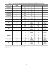
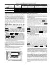
Table 8 illustrates how the control method and cooling set
point select variables direct the operation of the chiller and the
set point to which it controls. The illustration also shows the
ON/OFF state of the machine for the given combinations.
Cooling Set Point Select
SINGLE — Unit operation is based on Cooling Set Point 1
(CSP1) [Set Point, COOL].
DUAL SWITCH — Unit operation is based on Cooling Set
Point 1 (CSP1) [Set Point, COOL] when the Dual Set Point
switch contacts are open and Cooling Set Point 2 (CSP2)
[Set Point, COOL] when they are closed.
DUAL SCN OCCUPIED — Unit operation is based on
Cooling Set Point 1 (CSP1) [Set Point, COOL] during the
Occupied mode and Cooling Set Point 2 (CSP2) [Set Point,
COOL] during the Unoccupied mode as configured under the
local occupancy schedule accessible only from SCN. Schedule
Number in Table SCHEDOVR (See Appendix A) must be
configured to 1. If the Schedule Number is set to 0, the unit will
operate in a continuous 24-hr Occupied mode. Control method
must be configured to 0 (switch). See Table 8.
4 TO 20 mA INPUT — Unit operation is based on an external
4 to 20 mA signal input to the Energy Management Module
(EMM).
LOW SOUND MODE OPERATION — All models are fac-
tory configured with the Low Sound Mode disabled. In the
Configuration mode under sub-mode OPT2, items for low
sound mode select (LS.MD), low sound start time (LS.ST),
low sound end time (LS.ND) and low sound capacity limit
(LS.LT) are factory configured so that the chiller always runs
as quietly as possible. This results in operation at increased
saturated condensing temperature. As a result, some models
may not be able to achieve rated efficiency. For chiller opera-
tion at rated efficiency, disable the low sound mode or adjust
the low sound mode start and stop times accordingly or set both
times to 00:00 for rated efficiency operation 24 hours per day.
In addition, the low sound capacity limit can be used to reduce
overall chiller capacity, if required, by limiting the maximum to
a user-configured percentage.
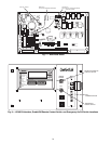
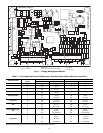
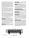
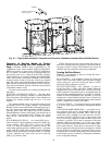
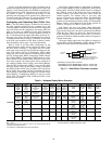
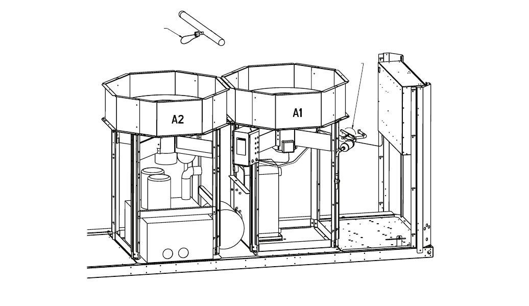
PRESSURE TRANSDUCER
INSTALLED HERE
SEE DETAIL A
DETAIL A
Fig. 15 — Typical Motormaster® V Controller and Pressure Transducer Location (Sizes 022-030 Shown)