


62
The amount of capacity reduction achieved by the mini-
mum load valve is not adjustable. The total unit capacity with
the minimum load valve is shown in Table 7.
PRESSURE RELIEF DEVICES — All units have one pres-
sure relief device per circuit located in the liquid line which re-
lieves at 210 F (100 C).
Compressor and Unit Protective Devices
MANUAL STARTER — There is one manual starter per
compressor in each unit. It protects the compressor(s) against
overloading, locked rotor conditions, and primary single phas-
ing. If the manual starter trips, determine the cause and correct
it before resetting.
Manual starters are factory set; field adjustment should not
be required. Manual starters are also factory installed for each
condenser fan motor and factory-installed chilled water pump.
NOTE: Two-speed condenser fan motors on sizes 010-018 and
032-040 have manual starters so that the motor is protected
while running in both low and high speed modes. Refer to
Appendix B for factory settings.
COMPRESSOR INTERNAL THERMAL PROTECTION —
All models include internal compressor protection. Models
using the SM110 compressor (015 50 Hz and 018 60 Hz) have
internal line break overloads. All other compressor models
have internal discharge temperature thermostats that are wired
in series with the compressor high pressure switch in the com-
pressor motor junction box. The thermostat opens and shuts off
the compressor if the discharge gas temperature exceeds 275 F
(135 C). The thermostat will automatically reset when the tem-
perature drops below a preset level, however, the control mod-
ule will keep the unit locked off until the alert condition is
reset.
Check Unit Safeties
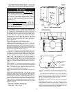
HIGH-PRESSURE SWITCH — A high-pressure switch is
provided to protect each compressor and refrigeration system
from unsafe high pressure conditions. See Table 32 for high-
pressure switch settings.
The high-pressure switch is mounted in the discharge side
of each compressor. A snubber is provided between the com-
pressor discharge manifold and the high-pressure switch to pre-
vent pressure pulsations from damaging the switch.
The high-pressure switch is mounted in the discharge line of
each compressor. If an unsafe, high-pressure condition should
exist, the switch opens and shuts off the affected compressor.
The compressor feedback signal to J9 of the MBB then opens
causing an alert condition. The MBB prevents the compressor
from restarting until the alert condition is reset. The switch
should open at the pressure corresponding to the appropriate
switch setting as shown in Table 32.
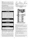
Table 32 — Factory Settings, High-Pressure
Switch (Fixed)
Clear the alarm using the Scrolling Marquee display as de-
scribed on page 42. The unit should restart after the compressor
anti-short-cycle delay, built into the unit control module,
expires.
PRESSURE TRANSDUCERS — Each refrigerant circuit is
equipped with a suction and discharge pressure transducer. The
transducers are NOT the same part number. The discharge
pressure transducer is the universal pressure transducer while
the suction pressure transducer is a discrete low pressure trans-
ducer. These inputs to the MBB are not only used to monitor
the status of the unit, but to also maintain operation of the chill-
er within the compressor manufacturer's specified limits. The
input to the MBB from the suction pressure transducer is also
used to protect the compressor from operating at low pressure
conditions. In some cases, the unit may not be able to run at full
capacity. The control module will automatically reduce the ca-
pacity of a circuit as needed to maintain specified maximum/
minimum operating pressures.
UNIT
CUTOUT CUT-IN
Psig kPa Psig kPa
30RA
426 ± 7 2937 ± 48 324 ± 20 2206 ± 138
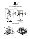
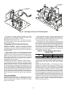
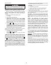
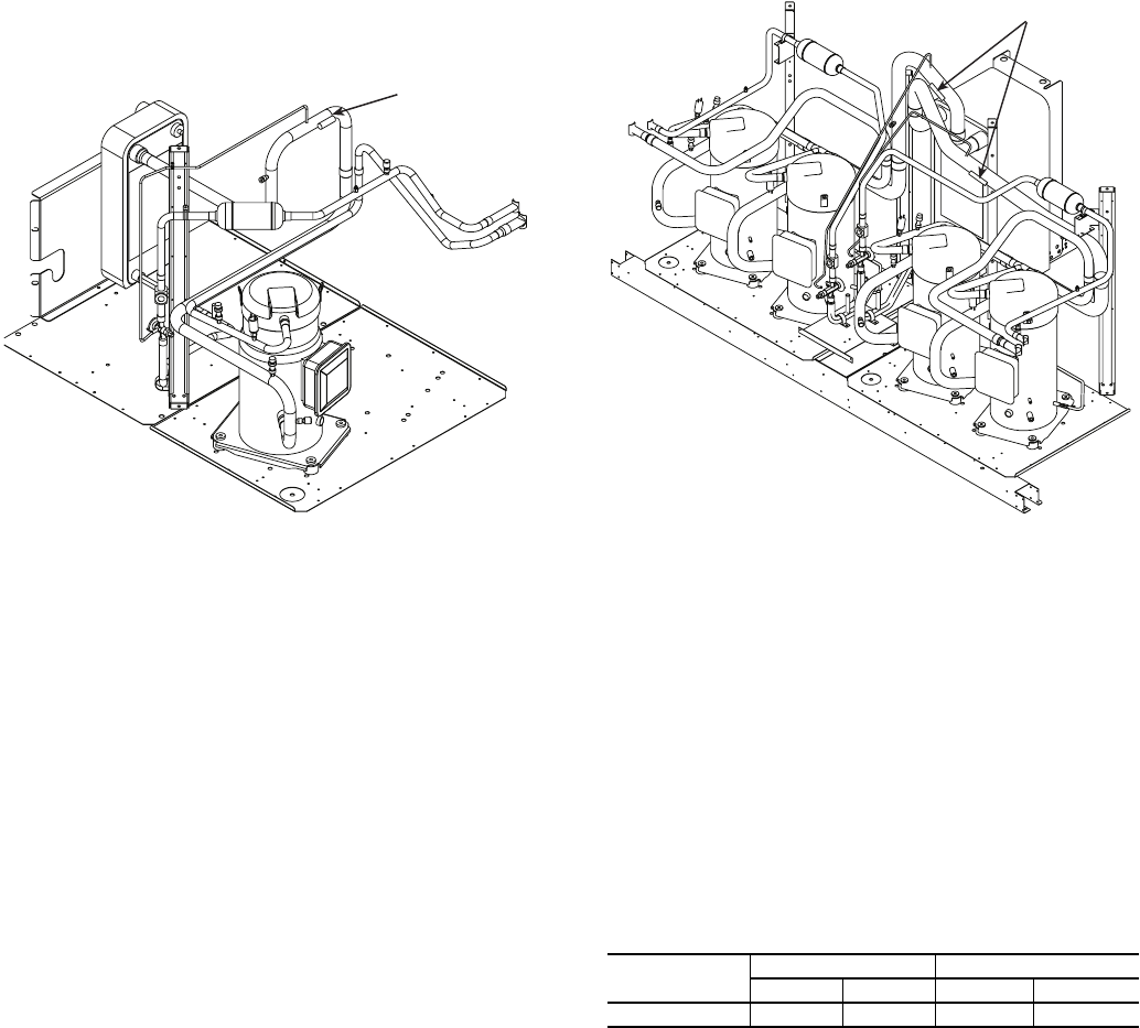
TXV SENSOR
LOCATION
TXV SENSOR
LOCATION
Fig. 34 — Mounting Locations for TXV Sensing Bulb