


44
2.0 F (1.1 C) cooler ∆T and 0° F (0° C) reset at 10.0 F (5.6 C)
cooler ∆T. The variable RT.NO should be set to the cooler
temperature difference (∆T) where no chilled water tempera-
ture reset should occur. The variable RT.F should be set to the
cooler temperature difference where the maximum chilled wa-
ter temperature reset should occur. The variable RM.DG
should be set to the maximum amount of reset desired.
To verify that reset is functioning correctly proceed to Run
Status mode, sub-mode VIEW, and subtract the active set point
(SETP) from the control point (CTPT) to determine the degrees
reset.
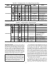
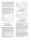
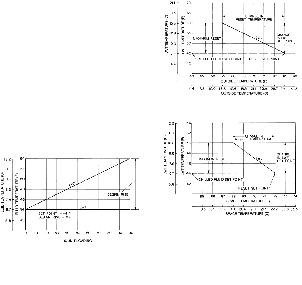
Under normal operation, the chiller will maintain a constant
leaving fluid temperature approximately equal to the chilled
fluid set point. As the cooler load varies, the entering cooler
fluid will change in proportion to the load as shown in Fig. 18.
Usually the chiller size and leaving-fluid temperature set point
are selected based on a full-load condition. At part load, the flu-
id temperature set point may be colder than required. If the
leaving fluid temperature was allowed to increase at part load,
the efficiency of the machine would increase.
Return temperature reset allows for the leaving temperature
set point to be reset upward as a function of the return fluid
temperature or, in effect, the building load.
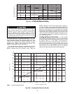
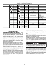
Figures 19 and 20 are examples of outdoor air and space
temperature resets.
Demand Limit —
Demand Limit is a feature that allows
the unit capacity to be limited during periods of peak energy us-
age. There are 3 types of demand limiting that can be config-
ured. The first type is through 2-stage switch control, which will
reduce the maximum capacity to 2 user-configurable percentag-
es. The second type is by 4 to 20 mA signal input which will re-
duce the maximum capacity linearly between 100% at a 4 mA
input signal (no reduction) down to the user-configurable level
at a 20 mA input signal. The third type uses the CNN Loadshed
module and has the ability to limit the current operating capaci-
ty to maximum and further reduce the capacity if required.
NOTE: The 2-stage switch control and 4- to 20-mA input sig-
nal types of demand limiting require the Energy Management
Module (EMM).
To use Demand Limit, select the type of demand limiting to
use. Then configure the Demand Limit set points based on the
type selected.
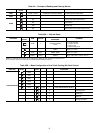
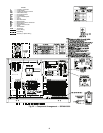
DEMAND LIMIT (2-Stage Switch Controlled) — To con-
figure Demand Limit for 2-stage switch control set the Demand
Limit Select (DMDC) [Configuration, RSET] to 1. Then
configure the 2 Demand Limit Switch points (DLS1 and DLS2)
[Configuration, RSET] to the desired capacity limit. See
Table 27. Capacity steps are controlled by 2 relay switch inputs
field wired to TB6 as shown in Fig. 4-6.
For Demand Limit by 2-stage switch control, closing the
first stage demand limit contact will put the unit on the first de-
mand limit level. The unit will not exceed the percentage of ca-
pacity entered as Demand Limit Switch 1 set point. Closing
contacts on the second demand limit switch prevents the unit
from exceeding the capacity entered as Demand Limit Switch
2 set point. The demand limit stage that is set to the lowest de-
mand takes priority if both demand limit inputs are closed. If
the demand limit percentage does not match unit staging, the
unit will limit capacity to the closest capacity stage.
To disable demand limit configure the DMDC to 0. See
Table 27.
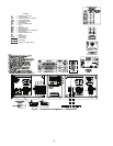
EXTERNALLY POWERED DEMAND LIMIT (4 to
20 mA Controlled) — To configure Demand Limit for 4 to 20
mA control set the Demand Limit Select (DMDC) [Configura-
tion, RSET] to 2. Then configure the Demand Limit at 20 mA
(DM20) [Configuration, RSET] to the maximum loadshed val-
ue desired. Connect the output from an externally powered 4 to
20 mA signal to terminal block TB6, terminals 1 and 5. Refer
to the unit wiring diagram for these connections to the optional/
accessory Energy Management Module and terminal block.
The control will reduce allowable capacity to this level for the
20 mA signal. See Table 27 and Fig. 21A.
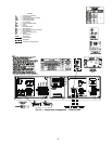
LEGEND
Fig. 18 — Standard Chilled Fluid
Temperature Control — No Reset
EWT —
Entering Water (Fluid) Temperature
LWT —
Leaving Water (Fluid) Temperature
LEGEND
LWT —
Leaving Water (Fluid) Temperature
Fig. 19 — Outdoor-Air Temperature Reset
LEGEND
LWT —
Leaving Water (Fluid) Temperature
Fig. 20 — Space Temperature Reset