


75
5. Allow unit to operate and confirm that everything is func-
tioning properly. Check to see that leaving fluid tempera-
ture agrees with leaving set point (CSP.1 or CSP.2), or if
reset is used, with the control point (CTPT) [Run Status,
VIEW].
6. Check the cooler leaving chilled water temperature to see
that it remains well above 32 F (0° C), or the brine freez-
ing point if the unit is a medium temperature brine unit.
7. Recheck compressor oil level (see Check Oil Charge
section).
Check Refrigerant Charge —
All 30RA units are
shipped with a complete operating charge of R-22 and should
be under sufficient pressure to conduct a leak test after installa-
tion. If there is no system pressure, admit nitrogen until a pres-
sure is observed and then proceed to test for leaks. After leaks
are repaired, the system must be dehydrated.
All refrigerant charging should be done through the ¼-in.
Schraeder connection on the liquid line. Do NOT add refriger-
ant charge through the low-pressure side of the system. If com-
plete charging is required, weigh in the appropriate charge for
the circuit as shown on the unit nameplate. If partial charging is
required, operate circuit at full load and use an accurate tem-
perature sensor on the liquid line as it enters the TXV. Use the
Temperatures mode on the Scrolling Marquee display to show
the circuit saturated condensing temperature (SCT.A or
SCT.B). Charging is most accurate at saturated discharge tem-
peratures of 120 to 125 F (49 to 52 C). Block condenser airflow
as required to reach this temperature range. Add refrigerant un-
til the system subcooling (SCT.A or SCT.B minus liquid line
temperature entering TXV) is approximately 15 to 17 F (–9.4
to –8.3 C). Refrigerant VAPOR only may be added to a circuit
through the
1
/
4
-in. suction Schraeder connection on the com-
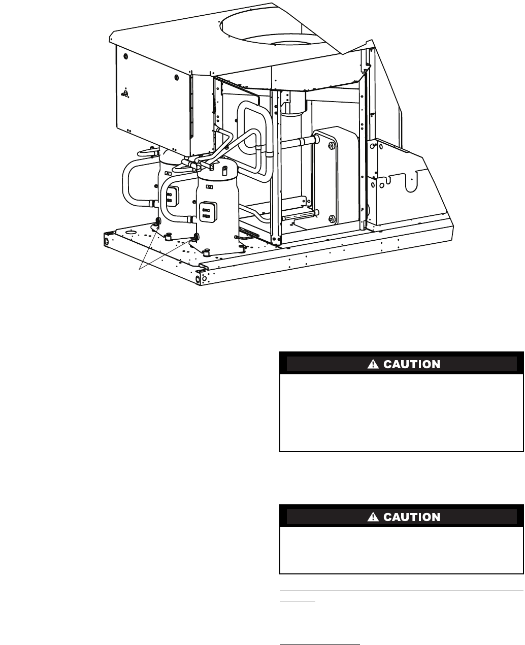
pressor. This connection is located in line and to the left of the
compressor junction box for the SM110 compressors and to the
lower right of the compressor junction box for all other com-
pressor models.
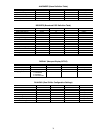
Operating Limitations
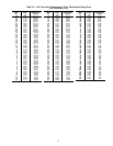
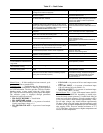
TEMPERATURES (See Table 41 for 30RA Standard Tem-
perature Limits)
High Cooler Leaving Chilled Water (Fluid) Temperatures
(LCWT) — During start-up with cooler LCWT above approx-
imately 60 F (16 C), the unit expansion valve will limit suction
pressure to approximately 90 psig (620 kPa) to avoid overload-
ing the compressor.
Low Cooler LCWT
— For standard units, the LCWT must be
no lower than 40 F (4.4 C). If the unit is the factory-installed
optional medium temperature brine unit, the cooler LCWT can
go down to 15 F (–9.4 C).
Never charge liquid into low-pressure side of system. Do
not overcharge. Overcharging results in higher discharge
pressure, possible compressor damage, and higher power
consumption. During charging or removal of refrigerant, be
sure water is continuously circulating through the cooler to
prevent freezing. Damage caused by freezing is considered
abuse and may void the Sterling warranty.
Do not operate with cooler leaving chiller water (fluid)
temperature (LCWT) below 40 F (4.4 C) for the standard
units, or below 15 F (–9.4 C) for units factory built for
medium temperature brine.
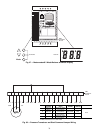
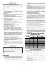
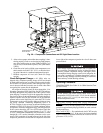
COMPRESSOR OIL
SIGHT GLASS
Fig. 39 — Compressor Connections and Oil Sight Glass Location