


73
REPLACING DEFECTIVE MODULES — The Comfort-
Link
™
replacement modules are shown in Table 39. If the Main
Base Board (MBB) has been replaced, verify that all configura-
tion data is correct. Follow the Configuration mode table and
verify that all items under sub-modes UNIT, OPT1 and OPT2
are correct. Any additional field-installed accessories or op-
tions (RSET, SLCT sub-modes) should also be verified as well
as any specific time and maintenance schedules.
Refer to the Start-Up Checklist for 30RA Liquid Chillers
(completed at time of original start-up) found in the job folder.
This information is needed later in this procedure. If the check-
list does not exist, fill out the current information in the Config-
uration mode on a new checklist. Tailor the various options and
configurations as needed for this particular installation.
1. Check that all power to unit is off. Carefully disconnect
all wires from the defective module by unplugging its
connectors.
2. Remove the defective module by removing its mounting
screws with a Phillips screwdriver, and removing the
module from the control box. Save the screws later use.
3. Verify that the instance jumper (MBB) or address switch-
es (all other modules) exactly match the settings of the
defective module.
NOTE: Handle boards by mounting standoffs only to avoid
electrostatic discharge.
4. Package the defective module in the carton of the new
module for return to Sterling.
5. Mount the new module in the unit’s control box using a
Phillips screwdriver and the screws saved in Step 2.
6. Reinstall all module connectors. For accessory Navigator
replacement, make sure the plug is installed at TB3 in the
LEN connector.
7. Carefully check all wiring connections before restoring
power.
8. Verify the ENABLE/OFF/REMOTE CONTACT switch
is in the OFF position.
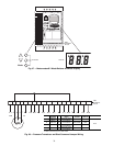
9. Restore control power. Verify that all module red LEDs
blink in unison. Verify that all green LEDs are blinking
and that the Scrolling Marquee or Navigator display is
communicating correctly.
10. Verify all configuration information, settings, set points
and schedules. Return the ENABLE/OFF/REMOTE
CONTACT switch to its previous position.
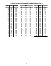
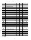
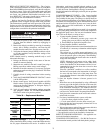
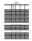
Table 39 — Replacement Modules
Hydronic Package —
If the unit is equipped with a
factory-installed hydronic package, consult the information be-
low for proper maintenance and service. In addition to this
information, each factory-installed hydronic package is sup-
plied with a packet of information supplied by the manufactur-
er, Bell & Gossett. Sterling/Sterlco strongly recommends
that this information be thoroughly reviewed prior to operation
of the chiller.
PUMP PERFORMANCE CHECK — The factory-installed
pumps in the 30RA units are shipped with a single impeller
size available for that pump. The pump was selected based on
the flow and head requirements as provided to Sterling. It is not
uncommon for actual pump duty to be different than what was
anticipated at time of selection. In many cases, it may be desir-
able to make some field modifications to obtain optimum
pump performance.
Before any pump modifications are made, it is recommend-
ed that actual pump performance be verified and compared to
the applicable pump curve. See base unit installation instruc-
tions. This can be done in a variety of ways:
1. If pump impeller diameter is known:
a. Connect a differential pressure gage across the
pump at the ports provided on the pump volutes.
b. Read GPM from applicable impeller curve.
2. If pump impeller diameter is not known:
If pump impeller diameter has been trimmed and the size
is not known, it is necessary to determine which impeller
curve to read.
The easiest way to confirm pump performance is to
“dead-head” the pump and read the differential pressure
across the pressure ports on the pump. “Dead-heading”
can be done by shutting the circuit setter valve on the dis-
charge side of the pump.
NOTE: Although not all pumps can be safely “dead-
headed”, centrifugal pumps (such as on the 30RA units)
can be “dead-headed” for short amounts of time. It is rec-
ommended to keep the time short due to excessive heat
build-up in the pump.
Since the “dead-head” condition is a no-flow condition,
the head will correspond to the intersection of an impel-
ler curve with the vertical axis of the pump chart. The
correct impeller diameter is that which corresponds to the
measured head.
3. Once the impeller diameter is known, proceed as in
Step 1.
4. Water flow rate can be determined by using a differential
pressure gage with the Bell & Gossett circuit setter bal-
ance valve calculator. (This information is also provided
in the installation instructions.) This method will not di-
rectly measure pressure differential seen by the pump, but
can be used to “double-check” the pump measurement.
5. Verify that cable connections at the switch and at the ter-
minal block are secure.
6. For factory-installed hydronic system, verify that:
• All air has been purged from the system.
• Circuit setter balance valve has been correctly set.
7. Pump impeller has been improperly trimmed and is not
providing sufficient flow.
8. Wrong pump motor rotation. Pump must rotate clockwise
when viewed from motor end of pump.
PUMP MODIFICATIONS AND IMPELLER TRIMMING
— See applicable section in the Installation instructions.
RESET OF CHILLER WATER FLOW — See applicable sec-
tion in the Installation instructions.
CHANGING OF PUMP SEALS — See Bell & Gossett ser-
vice instruction manual provided with the hydronic package.
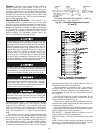
Electrical shock can cause personal injury. Disconnect all
electrical power before servicing.
MODULE
REPLACEMENT PART
NO. (with Software)
REPLACEMENT PART
NO. (without Software)
Main Base
Board (MBB)
30RA501102 HK50AA029
Scrolling
Marquee
Display
HK50AA031 HK50AA030
Energy
Management
Module
(EMM)
30GT515218 HK50AA028
Navigator
Display
HK50AA033 N/A