


58
SERVICE
Electronic Components
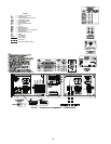
CONTROL COMPONENTS — Unit uses an advanced elec-
tronic control system that normally does not require service.
For details on controls refer to Operating Data section.
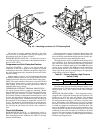
Access to the compressors is through latched panels from
beneath the control box on all models or from opposite the coil
side (sizes 010-030 only). The front door(s) provide access to
the compressor(s) and all components of the refrigeration sys-
tem. For size 010-030 units, access to the controls is through
the upper latched outer door above the compressor access door.
Similarly, the upper center latched door on sizes 032-055 gives
access to the controls. Inner panels are secured in place and
should not be removed unless all power to the chiller is off.
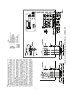
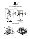
Compressor Replacement (Refer to Fig. 27-
30) —
All models contain scroll compressors and have from
one to four compressors. The size 010-030 units are a single re-
frigeration circuit while sizes 032-055 are dual circuit. A com-
pressor is most easily removed from the front of the unit, de-
pending on where clearance space was allowed during unit
installation.
Unscrew the junction box cover bolts and disconnect the
compressor power and ground connections. Remove the cable
from the compressor junction box. Remove the connections
from the internal thermostat and high-pressure switch (all com-
pressors except SM110) or high-pressure switch connections
(SM110 only). Knock the same holes out of the new compres-
sor junction box and install the cable connectors from the old
compressor. Remove the blockoff channel from below the con-
trol box.
Be sure the oil equalization line fitting is removed from the
old compressor and installed on the new compressor for those
models with dual compressor circuits. The compressors are
bolted to the unit basepan. Remove the 4 bolts holding the
compressor to the basepan. Save the mounting hardware for
use with the new compressor. Carefully cut the compressor
suction and discharge lines with a tubing cutter as close to the
compressor as feasible. For dual compressor circuits, do NOT
disturb the suction line tee at the backside of the compressors.
This tee contains a special tube that is required for proper oil
return. Remove high-pressure switch and pressure transduc-
er(s) if required for compressor removal. Lift one corner of the
compressor at a time and remove all the rubber mounting
grommets. Remove the old compressor from the unit.
Slide the new compressor in place on the basepan. Lifting
one side of the compressor at a time, replace all of the compres-
sor mounting grommets. Using new tubing or couplings as re-
quired, reconnect compressor suction and discharge lines. Us-
ing hardware saved, reinstall the mounting bolts and washers
through the compressor feet. Using proper techniques, braze
suction and discharge lines and check for leaks. Reconnect oil
equalization line on dual compressor circuit models.
Reconnect the compressor power connections and high-
pressure switch/internal thermostat wiring as on the old com-
pressor. Refer to Fig. 27-30. Following the installation of the
new compressor, tighten all hardware to the following specifi-
cations. (See Table 30.)
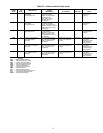
Table 30 — Unit Torque Specification
Cooler
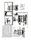
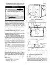
BRAZED-PLATE COOLER HEAT EXCHANGER RE-
PLACEMENT — Brazed-plate heat exchangers cannot be
repaired if they develop a leak. If a leak (refrigerant or water)
develops, the heat exchanger must be replaced. To replace a
brazed plate heat exchanger:
1. Disconnect the liquid-in and liquid-out connections at the
heat exchanger.
2. Check that the replacement heat exchanger is the same as
the original heat exchanger. The unit insulation covers the
manufacturer’s part number. Make sure the depths of the
replacement and original cooler heat exchangers are the
same.
3. Reclaim the refrigerant from the system, and unsolder the
refrigerant-in and refrigerant-out connections.
4. Remove the old heat exchanger and the bracket that it is
mounted to. The replacement heat exchanger is supplied
attached to a new mounting bracket and is fully insulated.
It also includes a cooler heater. Use of the heater is not re-
quired unless the original cooler contained a factory in-
stalled heater.
5. Install the replacement heat exchanger in the unit and at-
tach the mounting bracket hardware to the fan uprights
(sizes 010-030) or to the bottom bracket (sizes 032-055)
using the hardware removed in Step 4. Reconnect the
cooler heater if required.
6. Carefully braze the refrigerant lines to the connections on
the heat exchanger. Lines should be soldered using silver
as the soldering material with a minimum of 45% silver.
Keep the temperature below 1472 F (800 C) under nor-
mal soldering conditions (no vacuum) to prevent the cop-
per solder of the brazed plate heat exchanger from chang-
ing its structure. Failure to do so can result in internal
or external leakage at the connections which cannot be re-
paired.
7. Reconnect the water/brine lines.
8. Dehydrate and recharge the unit. Check for leaks.
BRAZED-PLATE COOLER HEAT EXCHANGER
CLEANING — Brazed-plate heat exchangers must be
cleaned chemically. A professional cleaning service skilled in
chemical cleaning should be used. Use a weak acid (5% phos-
phoric acid, or if the heat exchanger is cleaned frequently, 5%
oxalic acid). Pump the cleaning solution through the
exchanger, preferably in a backflush mode. After cleaning,
rinse with large amounts of fresh water to dispose of all the
acid. Cleaning materials must be disposed of properly.
The factory-installed strainer screen in front of the water/
brine inlets of the heat exchangers should be cleaned periodi-
cally, depending on condition of the chiller water/brine.
ELECTRIC SHOCK HAZARD.
Turn off all power to unit before servicing. The
ENABLE/OFF/REMOTE CONTACT switch
on control panel does not shut off control
power; use field disconnect.
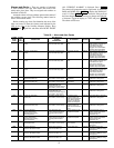
FASTENER RECOMMENDED TORQUE
Compressor Mounting
Bolts
10 to 14 ft-lb (13.5 to 18.9 N-m)
Compressor Power
Connections
24 to 28 in.-lb (2.7- to 3.2 N-m)
Compressor Ground
Terminal Connections
14 to 18 in.-lb (1.6 to 2.0 N-m)
Oil Equalization
Line Fitting
10 to 13 ft-lb (13.5 to 17.6 N-m)