


71
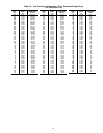
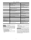
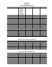
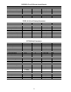
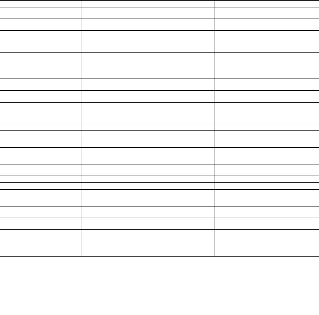
Table 37 — Fault Codes
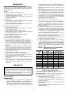
Manual Reset
— If fault condition has been removed, cycle
power to the chiller to reset the VFD.
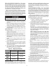
Troubleshooting
— Troubleshooting the Motormaster® V
control requires a combination of observing system operation
and VFD information. The drive provides 2 kinds of trouble-
shooting modes: a status matrix using the 3-digit display
(P57, P58) and real time monitoring of key inputs and outputs.
The collective group is displayed through parameters
50-60 and all values are read-only.
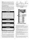
• P50: FAULT HISTORY — Last 8 faults
• P51: SOFTWARE version
• P52: DC BUS VOLTAGE — in percent of nominal.
Usually rated input voltage x 1.4
• P53: MOTOR VOLAGE — in percent of rated output
voltage
• P54: LOAD — in percent of drives rated output current
rating
• P55: VDC INPUT — in percent of maximum input:
100 will indicate full scale which is 5 v
• P56 4-20 mA INPUT — in percent of maximum input.
20% = 4 mA, 100% = 20 mA
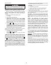
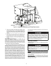
Manual Starter Trip
— If the VFD manual starter (MS-FC-
HS, MS-FC-A1 or MS-FC-B1 depending on model) trips,
locate the inrush current protectors (3 round black disks per
motor) and verify their resistance. For units operating at 208 v
or 230 v, these devices should measure approximately 7 ohms.
For all other voltages, they should measure approximately
20 ohms. Check value with mating plug disconnected, power
to chiller off and at ambient temperature (not hot immediately
after stopping VFD). These are standard resistances at 77 F
(25 C). Resistance values decrease at higher temperatures and
increase at lower temperatures.
FAULT CODE DESCRIPTION SOLUTION
AF High Temperature Fault: Ambient temperature is too high;
Cooling fan has failed (if equipped).
Check cooling fan operation
CF Control Fault: A blank EPM, or an EPM with corrupted data
has been installed.
Perform a factory reset using Parameter 48 —
PROGRAM SELECTION.
cF Incompatibility Fault: An EPM with an incompatible parame-
ter version has been installed.
Either remove the EPM or perform a factory
reset (Parameter 48) to change the parameter
version of the EPM to match the parameter
version of the drive.
CL CURRENT LIMIT: The output current has exceeded the
CURRENT LIMIT setting (Parameter 25) and the drive is
reducing the output frequency to reduce the output current.
If the drive remains in CURRENT LIMIT too long, it can trip
into a CURRENT OVERLOAD fault (PF).
Check for loose electrical connections.
Check for faulty condenser fan motor.
Check Parameter P25 from Table 38 is set cor-
rectly.
GF Data Fault: User data and OEM defaults in the EPM are
corrupted.
Restore factory defaults P48, see section
above. If that does not work, replace EPM.
HF High DC Bus Voltage Fault: Line voltage is too high; Decel-
eration rate is too fast; Overhauling load.
Check line voltage — set P01 appropriately
JF Serial Fault: The watchdog timer has timed out, indicating
that the serial link has been lost.
Check serial connection (computer)
Check settings for PXX.
Check settings in communication software to
match PXX.
LF Low DC Bus Voltage Fault: Line voltage is too low. Check line voltage — set P01 appropriately
OF Output Transistor Fault: Phase to phase or phase to ground
short circuit on the output; Failed output transistor; Boost
settings are too high; Acceleration rate is too fast.
Reduce boost or increase acceleration values.
If unsuccessful, replace drive.
PF Current Overload Fault: VFD is undersized for the applica-
tion; Mechanical problem with the driven equipment.
Check line voltage — set P01 appropriately
Check for dirty coils
Check for motor bearing failure
SF Single-phase Fault: Single-phase input power has been
applied to a three-phase drive.
Check input power phasing
F1 EPM Fault: The EPM is missing or damaged.
F2-F9, Fo Internal Faults: The control board has sensed a problem Consult factory
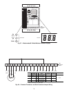
Drive display = 60.0 even though it
is cold outside and it should be run-
ning slower
Feedback signal is above set point Check for proper set point
Check liquid line pressure
Drive display = ‘---’ even though
drive should be running
Start jumper is missing Replace start jumper. See section above
Drive display = 8.0 even though fan
should be running faster
Feedback signal is below set point and fan is at minimum
speed
Check for proper set point
Check liquid line pressure
VFD flashes 57 and LCS Feedback or speed signal lost. Drive will operate at 57 Hz
until reset or loss of start command. Resetting requires
cycling start command (or power).
In stand alone mode: Check transducer wiring
and feedback voltage. Feedback voltage dis-
played on P-69. Pin 6 should be 5 v output.
Pin 5 (feedback) should be somewhere
between 0 and 5 v.