


21
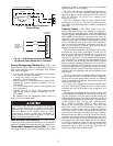
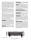
Head Pressure Control —
The Main Base Board
(MBB) controls the condenser fans to maintain the lowest
condensing temperature possible, and thus the highest unit
efficiency. The MBB uses the saturated condensing tempera-
ture input from the discharge pressure transducer to control the
fans. Head pressure control is maintained through a calculated
set point which is automatically adjusted based on actual
saturated condensing and saturated suction temperatures so
that the compressor(s) is (are) always operating within the
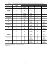
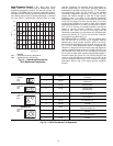
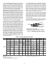
manufacturer's specified envelope (see Fig. 13). The control
will automatically reduce the unit capacity as the saturated
condensing temperature approaches an upper limit. The
control will indicate through an alert that a high ambient
unloading mode is in effect. If the saturated condensing
temperature in a circuit exceeds the calculated maximum, the
circuit will be stopped. For these reasons, there are no head
pressure control methods or set points to enter. If the saturated
condensing temperature in a circuit is greater than or equal to
95 F (35 C) at start-up, all available condenser fans will be
started to prevent excessive discharge pressure during
pull-down. The control will turn off a fan stage when the
condensing temperature has been below the calculated head
pressure set point by 35 F (19.4 C) for more than 2 minutes.
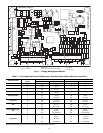
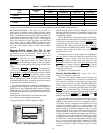
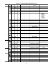
Fan sequences are shown in Fig. 14.
MOTORMASTER® V OPTION — For low-ambient opera-
tion, the lead fan on a circuit can be equipped with the
Motormaster V head pressure controller option or accessory.
The control will automatically raise the head pressure set point
by 5 F (2.8 C) when Motormaster control is configured. The
controller is energized with the first fan stage and adjusts fan
speed to maintain a liquid pressure of 135 psig (931 kPa). For
sizes 010-018 and Circuit B of sizes 032-040, the two-speed
fan is wired for high speed operation and the Motormaster V
controller adjusts fan speed. For size 022-030, 042-055 and
circuit A of the 032-040 sizes, the lead fan (A1 or B1) in the
circuit is controlled. Refer to Fig. 14 for condenser fan staging
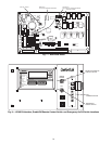
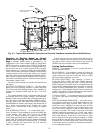
information. Refer to Fig. 15 for typical pressure transducer
location.
LEGEND
Fig. 13 — Operating Envelope for
R-22 Maneurop Compressor
SCT —
Saturated Condensing Temperature
SST —
Saturated Suction Temperature
-10 -5
40
60
80
100
120
160
140
05
10
15
20
25 30
35 40 45 50 55
R-22 SST (F)
SCT (F)
105
149
47.5
154
78
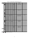
FAN ARRANGEMENT FAN NO. FAN RELAY NORMAL CONTROL
30RAN010-018
1FC-LS
Energize Fan at
Low Speed
1FC-HS
Energize Fan at
High Speed
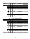
30RAN022-030
1FC-A1
First Stage
Condenser Fan
2FC-A2
Second Stage
Condenser Fan
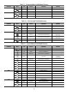
30RAN032-040
1FC-A1
On with Compressor A1
and/or Compressor A2
2FC-A2
First Stage Condenser
Fan, Circuit A
3FC-LS
Low Speed, Fan on
w/Compressor B1
3FC-HS
Energize Fan at High Speed,
Circuit B
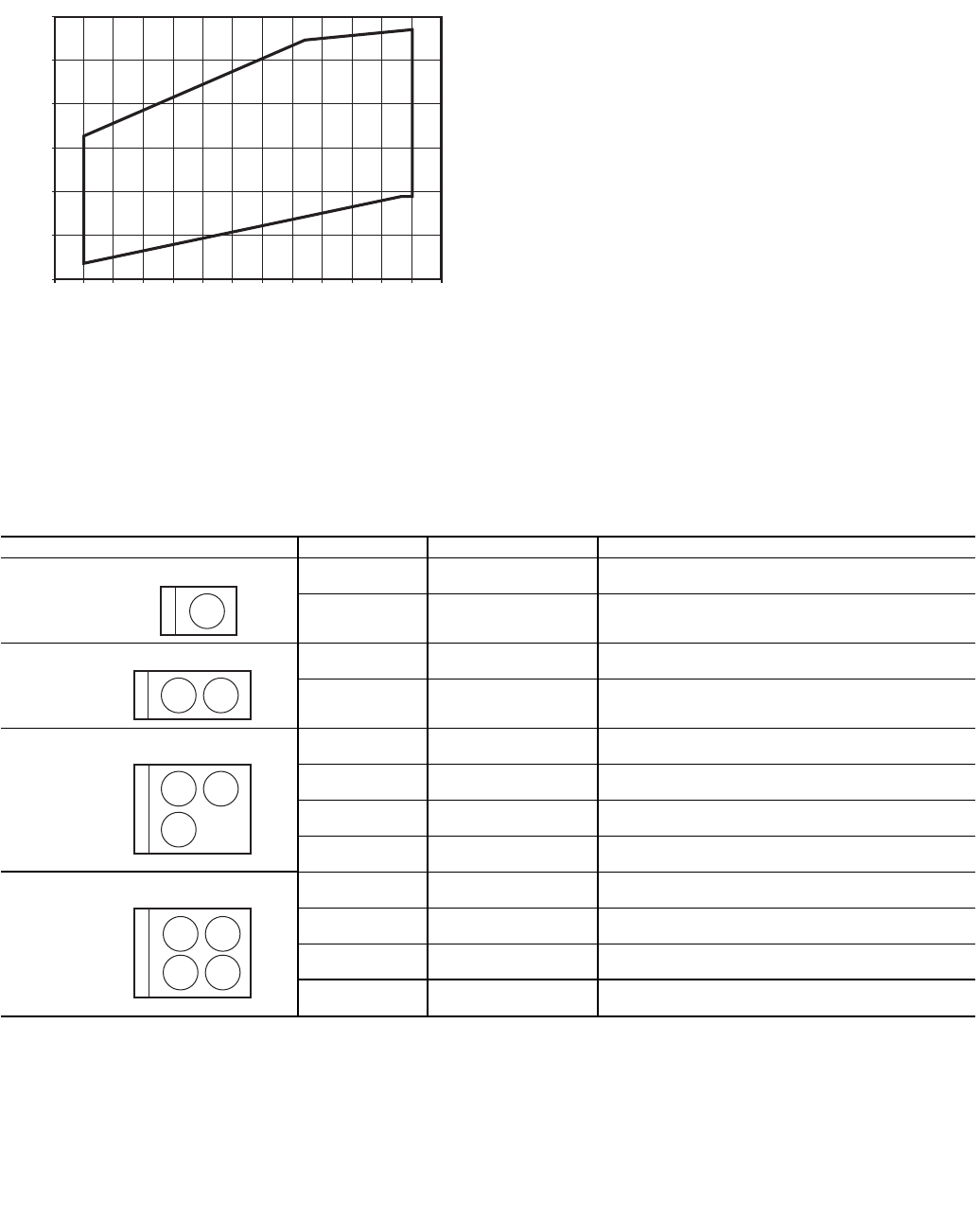
30RAN042-055
1FC-A1
On with Compressor A1
and/or Compressor A2
2FC-A2
First Stage Condenser Fan,
Circuit A
3FC-B1
On with Compressor B1
and/or Compressor B2
4FC-B2
First Stage Condenser Fan,
Circuit B
CONTROL
BOX
END
1
CONTROL
BOX
END
1 2
1 2
CONTROL
BOX
END
3
CONTROL
BOX
END
1 2
3 4
Fig. 14 — 30RA Condenser Fan Sequence