


63
COOLER FREEZE-UP PROTECTION
The Main Base Board (MBB) monitors leaving fluid tem-
perature at all times. The MBB will rapidly remove stages of
capacity as necessary to prevent freezing conditions due to the
rapid loss of load or low cooler fluid flow.
When the cooler is exposed to lower ambient temperatures
(34 F [1° C] or below), freeze-up protection is required using
inhibited ethylene glycol.
HEATER CABLE — Optional factory-installed cooler and/or
hydronic package heaters are cycled based on the input from
the outside-air temperature sensor. These heaters, when in-
stalled, are designed to protect the cooler and/or hydronic pack-
age from freezing down to –20 F (–29 C). Power for these heat-
ers is supplied from the main unit power.
The input from the low pressure transducer provides a back-
up cooler freeze protection package. The MBB shuts down the
unit when a low pressure condition exists that could cause the
cooler to freeze up.
WINTER SHUTDOWN — At the end of the cooling season:
1. Drain the water/brine from the cooler, hydronic package
(if installed) and internal piping.
2. Fill the package with at least 2 gallons (7.6 L) of ethylene
glycol or other suitable uninhibited antifreeze solution to
prevent any residual water in the cooler and hydronic
package/piping from freezing.
3. At the beginning of the next cooling season, refill the
cooler and add the recommended inhibitor.
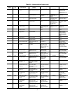
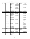
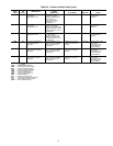
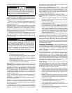
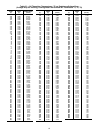
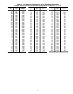
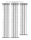
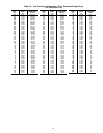
Thermistors —
Electronic control uses up to five 5 kΩ
thermistors to sense temperatures used to control operation of
the chiller. Thermistors T1, T2 and T9 are identical in their
temperature and voltage drop performance. Accessory return
gas thermistors are also 5 kΩ thermistors used to troubleshoot
TXV superheat settings. Thermistor T10 has a 10 kΩ input
channel and has a different set of temperature vs. resistance and
voltage drop performance. Resistance at various temperatures
are listed in Tables 33-36.
NOTE: For dual chiller operation, the control automatically
configures the T10 input channel to be a 5 kΩ channel. A
HH79NZ014 or HH79NZ029 thermistor should be used for
dual chiller configurations.
Thermistor pin connection points are shown in Table 2. Ther-
mistor T1 is located in a well at the bottom of the brazed plate
heat exchanger for sizes 010-030 and in the leaving fluid pip-
ing for sizes 032-055.
Thermistor T2 is located in a well at the top of the brazed
plate heat exchanger for sizes 010-030 and in the entering fluid
piping for sizes 032-055. Thermistor T9 is factory installed in
the compressor section behind a panel with a vent plug so that
outside air flows across the sensor tip.
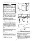
REPLACING THERMISTORS T1 and T2 — Add a small
amount of thermal conductive grease to the thermistor well and
end of probe. Thermistors are friction-fit thermistors, which
must be slipped into receivers in the cooler (010-030) or fluid
piping (032-055). For sizes 032-055, tighten the retaining nut
¼ turn past finger tight. See Fig. 35.
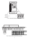
THERMISTOR/TEMPERATURE SENSOR CHECK — A
high quality digital volt-ohmmeter is required to perform this
check.
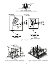
1. Connect the digital voltmeter across the appropriate
themistor terminals at the J8 terminal strip on the Main
Base Board (see Fig. 36).
2. Using the voltage reading obtained, read the sensor tem-
perature from Tables 33-36.
3. To check thermistor accuracy, measure temperature at
probe location with an accurate thermocouple-type tem-
perature measuring instrument. Insulate thermocouple to
avoid ambient temperatures from influencing reading.
Temperature measured by thermocouple and temperature
determined from thermistor voltage reading should be
close, ± 5° F (3° C) if care was taken in applying thermo-
couple and taking readings.
If a more accurate check is required, unit must be shut down
and thermistor removed and checked at a known temperature
(freezing point or boiling point of water) using either voltage
drop measured across thermistor at the J8 terminal, by deter-
mining the resistance with chiller shut down and thermistor
disconnected from J8. Compare the values determined with the
value read by the control in the Temperatures mode using the
Scrolling Marquee display.
Pressure Transducers —
Suction and discharge pres-
sure transducers are installed on each circuit. No pressure
transducer calibration is required. The transducers operate on a
5 vdc supply, which is generated by the Main Base Board
(MBB). See Fig. 36 for transducer connections to the J8 con-
nector on the MBB.
TROUBLESHOOTING — If a transducer is suspected of be-
ing faulty, first check the supply voltage to transducer. Supply
voltage should be 5 vdc ± 0.2 v. If supply voltage is correct,
compare pressure reading displayed on the Scrolling Marquee
display module against pressure shown on a calibrated pressure
gauge. Suction pressure should be within ± 2 psig. Discharge
pressure should be within ± 5 psig. If the two readings are not
reasonably close, replace the pressure transducer.
Flow Sensor —
A flow switch is factory installed in the
leaving fluid piping of all models. If the unit is equipped with
an optional hydronic system, the flow switch is inside the
pump cabinet. If nuisance trips of the sensor are occurring, fol-
low the steps below to correct the situation:
1. Check to confirm that the factory installed strainer is
clean. Use the blow-down valve provided or remove the
screen and clean it. For the case of VFD controlled
pumps, ensure that the minimum speed setting has not
been changed.
2. Measure the pressure drop across the cooler or cooler/
pump system and compare this to the system requirements.
3. Verify that cable connections at the switch and at the ter-
minal block are secure.
4. For factory-installed hydronic systems, verify that:
• All air has been purged from the system
• Circuit setter balance valve has been correctly set
5. Pump impeller has been improperly trimmed and is not
providing sufficient flow.
6. Wrong pump motor rotation. Pump must rotate clockwise
when viewed from motor end of pump.
On medium temperature brine units, the brine must be
properly mixed to prevent freezing at a temperature of at
least 15 F (8.3 C) below the leaving-fluid temperature set
point. Failure to provide the proper brine mixture is consid-
ered abuse and may void the Sterling warranty.
Do not disconnect main unit power when servicing com-
pressor(s) if ambient temperature is below 40 F (4.4 C).
Each compressor manual starter has a lockout feature.
Depress the Stop Button and pull the lockout tab from the
start button. Secure lock in place. If power to the unit must
be off for a prolonged period, drain the cooler, hydronic
package (if installed) and internal piping. Add glycol
according to WINTER SHUTDOWN Step 2 below.