


UPPER OVEN - RST Models
RC231002 Rev. 3 100
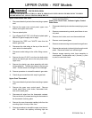
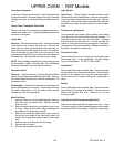
PROBLEMS POSSIBLE CAUSE CORRECTION
1. Oven Burner will not
turn on.
No 120 VAC to range.
Inoperative ignitor.
Inoperative gas valve.
Inoperative thermostat.
Faulty wiring.
Check electric at wall outlet.
Check ignitor according to instr
u
Check gas valve according to i
n
valve.
Check thermostat according to i
thermostat..
Check wiring against appropriat
e
sure all terminals and connectio
n
2. Gas valve opens but
burner does not ignite.
Bake ignitor positioned to far
from burner.
Reposition bake ignitor closer to
Adjust universal orifice accordin
g
installation instructions.
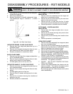
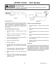
Electric Ignitor Test
The operating of the Oven "ELECTRIC IGNITOR" can be
checked by using a Volt/Ohmmeter as follows: NOTE:
This check must be made while the ignitor is at ambient
room temperature. It is a continuity check of the ignitor.
1. Disconnect electricity. (Disconnect plug or power
cord.)
2. Set the volt/ohmmeter on the RX1K ohms scale.
(Zero the meter.)
3. Attach one (1) lead of the volt/ohmmeter to any white
wire.
4. Remove the electric ignitor wire terminal from the
ELECTRIC GAS VALVE. (Refer to the appropriate
wiring diagram to determine the correct ignitor wire
terminal.)
5. Attach the remaining meter lead to the ignitor wire
terminal removed from the ELECTRIC GAS VALVE.
6. If the meter indicated "0" OHMS the ignitor is opera-
tive.
7. Reconnect wire terminals according to the appropri-
ate wiring diagram.
FIRE OR EXPLOSION
TO AVOID THE RISK OF ELECTRICAL SHOCK, PERSONAL INJURY OR DEATH DISCONNECT POWER
BEFORE SERVICING, UNLESS TESTING REQUIRES IT.
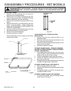
OPERATING AND TROUBLESHOOTING
PROCEDURES
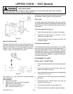
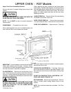
Upper Oven Controls
The upper oven controls consist of a thermostat, electric gas
valve, and a 120 VAC electric ignitor to provide ignition for
the gas at the oven burner.