


OPERATION AND SERVICE PROCEDURES
RC231002 Rev. 3 76
TO AVOID THE RISK OF ELECTRICAL SHOCK, PERSONAL INJURY OR DEATH DISCONNECT POWER
BEFORE SERVICING, UNLESS TESTING REQUIRES IT.
The "HI" position provides a flame which will bring water to
a full boil quickly. This is the "full on" position of the valve.
If the burner flame is turned down, an audible "click" can be
heard as the valve reaches the "MEDIUM" position. This
flame is sufficient to keep water boiling in a covered pan.
When the flame is turned down still lower, a second "click"
can be heard. This is a very low or "Keep Warm" flame
setting which is the "LO" position on the valve. The low
flame provides a warming heat to keep food which is
already cooked ready to serve.
The Tri-Set valves are equipped with metered, fixed
orifices and the low setting cannot be adjusted. As there
are air shutters, the burner flames can be adjusted in
accordance with the Adjustment and Calibration Instruc-
tions of this Manual.
The HI-LOW valves on other models are similar but
without the "click" stops.
TOP BURNER
The top burners consist of a burner and intergral cap, a
flash tube and support, a gas delivery tube including
venturi and an adjustment air shutter. These burners are
designed for trouble free operation with a minimum of
parts.
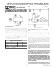
INDICATOR LIGHT TESTING
If the oven (bake, broil, clean) operates normally but the
indicator lights do not glow, check for voltage at the
indicator light terminals. If voltage is present at the
indicator terminals and the indicator does not glow, replace
the indicator light. If no voltage is present at the indicator
terminals, check for loose connectors, broken wiring, or
other defective components (thermostat, ignitor, etc.).
NOTE: The oven indicator light and the clean indicator
light operates on 120 VAC. Use caution when checking for
indicator light voltages.
OVEN LIGHT SWITCH
The oven light switch can be tested using the same
procedure as the fluorescent light switch.
The fluorescent light components, oven light switch and
indicator lights are located behind the backguard glass
mounted to the backguard control panel.
The indicator lights, oven light switch, selector switch, and
thermostat on RST307, 308, 309 are located behind the
control panel.
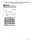
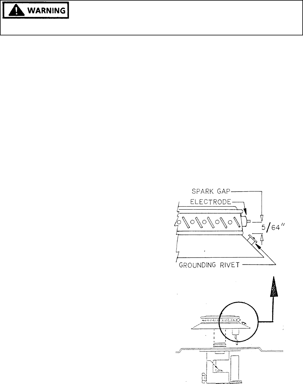
BURNER CAPS
Models with Sealed Burners
The burner caps on models with sealed burners contain the
electrode tip for the spark ignition.
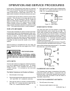
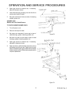
TO CHECK THE BURNER CAP:
1. Turn off power to the unit.
2. Remove burner cap from unit. Attach one of the
ohmmeter leads (RX1 scale) to the electrode termi-
nal. Attach the other lead to the tip of the electrode.
Continuity (low ohms) should be indicated. If continu-
ity is indicated, remove one (1) lead and attach lead
to the burner cap. Infinite ohms (open) should be
indicated.
Figure 76
Figure 77