


OPERATION AND SERVICE PROCEDURES
RC231002 Rev. 3 62
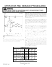
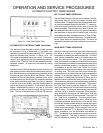
either timer switch contacts 1 to 2 or 3 to 4. Press
"SET" button twice (Auto Program) and rotate "SET"
knob for approximately ten (10) to fifteen (15) sec-
onds. Meter needle should swing to zero (0) ohms
(continuity) indicating a closed switch. Repeat the
procedure after transferring the test leads to the other
switch contacts. Allow countdown to complete, the
alarm should sound, and the meter indicate open
contacts. NOTE: A slight "click" can be heard
whenever the relay switches open or close.
TO AVOID THE RISK OF ELECTRICAL SHOCK,
PERSONAL INJURY OR DEATH DISCONNECT POWER
BEFORE SERVICING, UNLESS TESTING REQUIRES
IT.
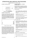
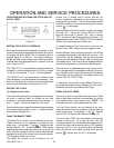
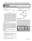
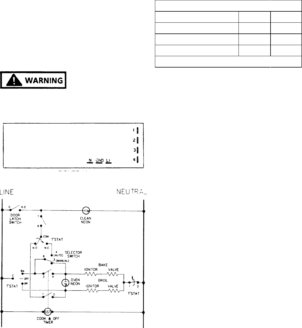
Figure 63 - Cook And Off Timer - Rear View - Partial
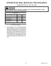
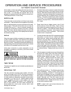
Figure 64 - Cook And Off Timer Switch Circuits
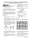
CLOCK TIMER
FUNCTION 1 - 2 3 - 4
MANUAL
0 0
COOKING IN AUTO
X X
AUTO COMPLETE
0 0
O = OPEN X = CLOSED
Timer Switching Schedule
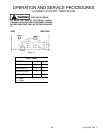
BAKE AND BROIL IGNITORS
The bake and broil ignitors are mounted to the bake and
broil burners and ignite the gas flowing into the burner.
During a broil or manual bake operation, current flows
through the ignitor, gas valve, selector switch, and thermo-
stat to neutral. As the ignitor starts heating up and glowing,
its internal resistance decreases allowing more current to
flow through the bake or broil circuit. When the circuit
current reaches approximately 3.2 - 3.6 amps, the bi-metal
arm in the gas valve flexes, opening the valve, allowing
gas to flow to the burner where it is ignited by the glowing
ignitor. The ignitors will glow anytime the bake or broil
burners are in operation and cycle on and off with the
thermostat cycling contacts.
The operation of the OVEN/BROILER "ELECTRIC IGNI-
TOR" can be checked by using a VOLT/OHMMETER as
follows: NOTE: This check must be made while the ignitor
is at ambient room temperature.
1. Disconnect electricity.
2. Set the volt/ohmmeter on the RX1K ohms scale.
(Zero the meter.)
3. Remove ignitor from burner.
4. Remove ignitor lead wire nuts and disconnect ignitor
leads from range wiring.
5. Connect ohmmeter leads to ignitor wire leads.
6. If the meter indicates continuity (a low resistance
reading), the ignitor is operative. NOTE: The cold
resistance measurement can vary several hundred
ohms. However, this test is for continuity without a
dead short (zero ohms).