


FIRE OR EXPLOSION - TO AVOID THE RISK OF ELECTRICAL SHOCK, PERSONAL
INJURY, OR DEATH, DISCONNECT POWER TO THE OVEN BEFORE SERVICING.
DISASSEMBLY PROCEDURES - RST MODELS
RC231002 Rev. 3 96
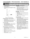
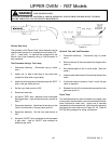
CLOCK/TIMER WIRE HARNESS (Ribbon Cable
Removal)
Models RST307, RST308, RST309
The wire harness (ribbon cable) for the clock is routed down
the left side of the range behind the left side panel. Follow
the procedures below to replace the cable.
1. Shut off power to the range.
2. Remove the range from the cabinet.
3. Partially remove the control panel. Follow the Control
Panel Removal Procedures, Steps 3 - 5.
4. Disconnect the wire harness plug connector from the
back of the clock display board.
5. Remove the storage drawer.
6. Remove the P.C. board cover mounting screw and
disconnect the wire harness plug connector from the
P.C. board.
7. Remove the three (3) left side burner box mounting
screws.
8. Remove left side panel to gain access to cable.
9. Reverse procedure to install clock cable.
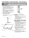
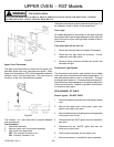
SIDE PANEL REPLACEMENT
NOTE: Left or right side panel should be replaced one at
a time. Do not attempt to remove both side panels as lack
of support may cause subsequent damage/twist to
backguard.
1. Disconnect electrical supply at wall socket.
2. In most installations the "gas has to be turned off" and
supply line disconnected from range. PULL RANGE
FORWARD.
3. Remove oven door assembly and storage drawer
assembly, burner grates and burner bowls.
4. Remove top burner grates, main top, and the one (1)
screw securing control panel to side panel (screws
located top left or top right of control panel).
5. Remove the three (3) screws securing side panel to
burner box.
6. Support range off floor 4-6 inches, then remove the
four (4) screws from bottom flange of side panel.
7. Remove the rear backguard cover panel.
8. Remove the four (4) screws securing backguard
support to side panel.
9. Remove the five (5) screws securing rear of side
panel to insulation retainer.
10. Remove the six (6) screws securing front of side
panel to front flame flange.
11. Move rear of side panel away from range, then move
side panel forward to clear flange on front frame.
12. Reverse procedure to reinstall side panel.
BE CERTAIN TO CHECK GAS CONNECTION WITH
LEAK DETECTOR OR WARM SOAPY WATER.
BOTTOM BRACE
1. Shut off power to the range.
2. Shut off main gas supply and disconnect supply line
from range. Pull range forward.
3. Remove oven door assembly and storage drawer
assembly. Remove top burner grates and burner
bowls.
4. Support range four (4) to six (6) inches off of floor.
Remove four (4) screws securing bottom brace to
side panel.
5. Remove two (2) screws securing brace to front frame.
6. Reverse procedure to install new brace. Screw
leveling legs into replacement brace.
Be sure to level range after installation. Check gas
connection for leaks with leak detector or soapy
water.
STORAGE DRAWER TRACK
1. Shut off power to the range.
2. Remove storage drawer.
3. Storage drawer track is fastened to the front frame
with one (1) screw. The track fits into a slot in the rear
insulation retainer. NOTE: The "TAB" on the front of
the drawer track and the storage drawer runner
"CATCH" are color coded. When reassembling, be
sure to match black "TAB" to black "CATCH" and gray
"TAB" to gray "CATCH".
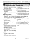
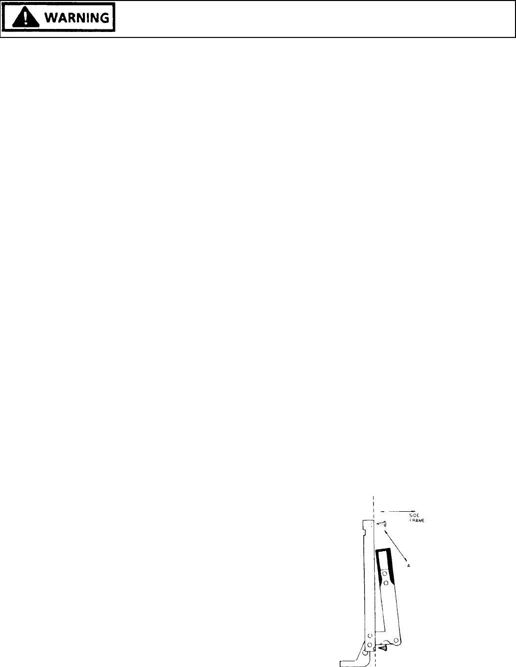
OVEN DOOR HINGE
1. Remove oven door assembly from the range.
2. Remove the two (2) screws securing the hinge to the
side frame.
3. Carefully open the hinge fully, and insert an object the
approximate thickness of a screw in slot under door
lock to keep hinge open. NOTE: Be careful not to
allow the object to slip out, causing the hinge to snap
back, possibly causing injury to the installers fingers.
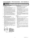
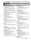
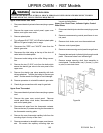
Figure 87 - Left Side View (Closed)