


FIRE OR EXPLOSION - TO AVOID THE RISK OF ELECTRICAL SHOCK, PERSONAL
INJURY, OR DEATH, DISCONNECT POWER TO THE OVEN BEFORE SERVICING.
DISASSEMBLY PROCEDURES - RST MODELS
RC231002 Rev. 3 94
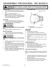
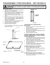
TOP BURNER SPARK IGNITORS (RSS MODELS)
1. Disconnect electricity at main disconnect plug.
2. Remove top burner grates and main top.
3. Remove top burner assembly (right and left).
4. Remove control panel.
5. Remove eight (8) right screws securing burner box in
place.
6. Gently maneuver control panel to free burner box.
7. Disconnect high voltage ignitor leads from spark
module.
8. Remove two (2) screws securing the top burner
mounting support to the burner box.
9. Straighten tabs on the ignitor grounding bracket and
remove bracket from the top burner mounting sup-
port.
10. Remove speed clip securing the spark ignitor to the
top burner mounting bracket (Clip must be re-used,
do not break.)
11. Reverse procedure to reinstall new top burner ignitor.
NOTE: Be certain the ignitor grounding bracket is
tight on the top burner support. Also be sure the gap
between the ignitor grounding bracket dimple and top
of ignitor is 1/8" (-1/32" + 0").
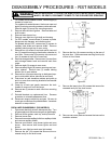
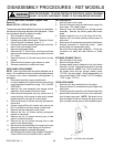
BURNER BOX
Sealed Burner Models
1. Shut off power to the range. Shut off main gas supply.
2. Remove grates, burner caps, and main top.
3. Remove six (6) screws securing burner box to side
panels.
4. Remove control panel. Remove two (2) screws
securing manifold to filler trim.
5. Disconnect two (2) feed tubes to manifold.
6. Lift up burner box and disconnect electrode leads at
spark module.
7. To replace the burner box, remove venturi assem-
blies and electrode leads, burner box baffles with
seal, manifold and tubing to venturi. Reassemble
components on replacement burner box. Be sure
baffle seal is correctly positioned.
Check all gas connections for gas leaks with leak
detector after reassembly.
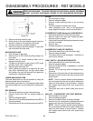
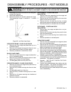
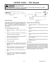
TOP BURNER VENTURI
Sealed Burners
1. Shut off power to the range. Shut off main gas supply
to the range.
2. Remove grates, burner caps, and main top.
3. Disconnect feed tube from burner valve to venturi.
4. Remove two (2) screws securing venturi to burner
box.
5. Remove screw securing mounting bracket to venturi
and remove electrode from bracket.
Be sure to check venturi feed tube connection for gas
leaks with leak detector after reassembly.
ELECTRODE WIRE WITH SOCKET
Sealed Burner Units (Aluminum Tubing Gas Feed)
1. Shut off power to the range. Shut off main gas supply
to the range.
2. Remove grates, burner caps, and main top.
3. Disconnect tube to venturi. Remove two (2) screws
securing venturi assembly to burner box.
4. Remove screw securing mounting bracket to venturi
assembly and remove electrode socket.
5. Remove burner box.
6. Disconnect electrode at spark module.
Check gas connections for leaks with leak detector
after reassembly.
BURNER BOX BAFFLE
Sealed Burner Models (Only On Aluminum Tubing
Gas Feed)
1. Shut off power to the range.
2. Remove grates, burner caps, and main top.
3. Remove three (3) screws securing baffle to burner
box. Baffle and silicone seal can now be removed.
Silicone seal must be located on baffle to assure
proper top burner operation.
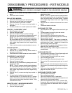
SPARK MODULE (FREE STANDING MODELS)
1. Disconnect electricity at main disconnect plug. Shut
off main gas supply to the range.
2. Remove main top.
3. Remove burner box.
4. Remove two (2) screws securing spark module bracket
to insulation retainer.
On models without sealed burners, the spark module
is located on the left side of the range.
The sealed burner models incorporate a spark mod-
ule on both the left and right sides of the range or one
(1) spark module with four (4) outputs on left side.
5. Remove screw securing module to mounting bracket.
Bend retaining tab to remove module from bracket.
6. Disconnect wire leads to module.
Check wiring diagram for proper wire identification
when reinstalling.
Check gas connections for leaks with leak detector or
soap solution.