


INSTALLATION INSTRUCTIONS
15 RC231002 Rev. 3
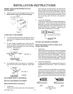
FLAME APPEARANCE
The air shutter (see Figure 17) should be adjusted for a
proper flame. Adjust the shutter so the flame has an inner
cone of bluish-green and an outer mantle of dark blue. The
flame should be soft in character.
NOTE: On LP gas a slight yellow tip will be visible on top
burner flames, but will not affect burner performance.
MODELS WITH SEALED TOP BURNERS
NOTE: Sealed Top Burner Models with Serial Number
Date Codes F006 through F009 are for use on Natural Gas
only and are not field convertible for use on LP gas.
TOP BURNER ADJUSTMENT (Below Serial Number
F0430127550)
ORIFICES
Universal Models (Natural or LP) are shipped from the
factory orificed for Natural Gas. IF THEY ARE TO BE
USED ON LP GAS, the burner orifice spuds must be
changed. They will be found wired to the inlet pipe behind
the storage drawer. The proper orifice for use on Bottled
(LP) Gas is red colored and stamped #68 (drill size). BE
SURE to use proper burner spud for the gas in use. Rewire
the Natural Gas orifice spuds to the inlet pipe for future
conversion.
Nat. Gas LP Gas
Burner Spud 54 68
(Red colored for
identification)
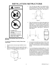
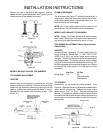
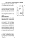
TO CONVERT
Remove four (4) top burners by pulling upwards. (See
Figure 26.) Remove the two (2) flat headed screws at each
burner and lift off main top. Replace the burner orifice
spuds using a 5/16" nut driver. Reinstall maintop and
burners. To replace the burners, position the ignitor over
the hole at the rear of each burner opening and push the
burner down onto the burner base until the skirt contacts
the maintop.
Figure 26
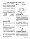
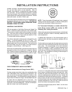
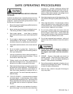
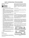
Remove the cap in the body of the regulator, over the
washer and spring, and tighten cap. See Figure 13 for the
correct position of the washer and spring.
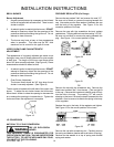
Figure 23
OR
Figure 24
MODELS WITHOUT SEALED TOP BURNERS
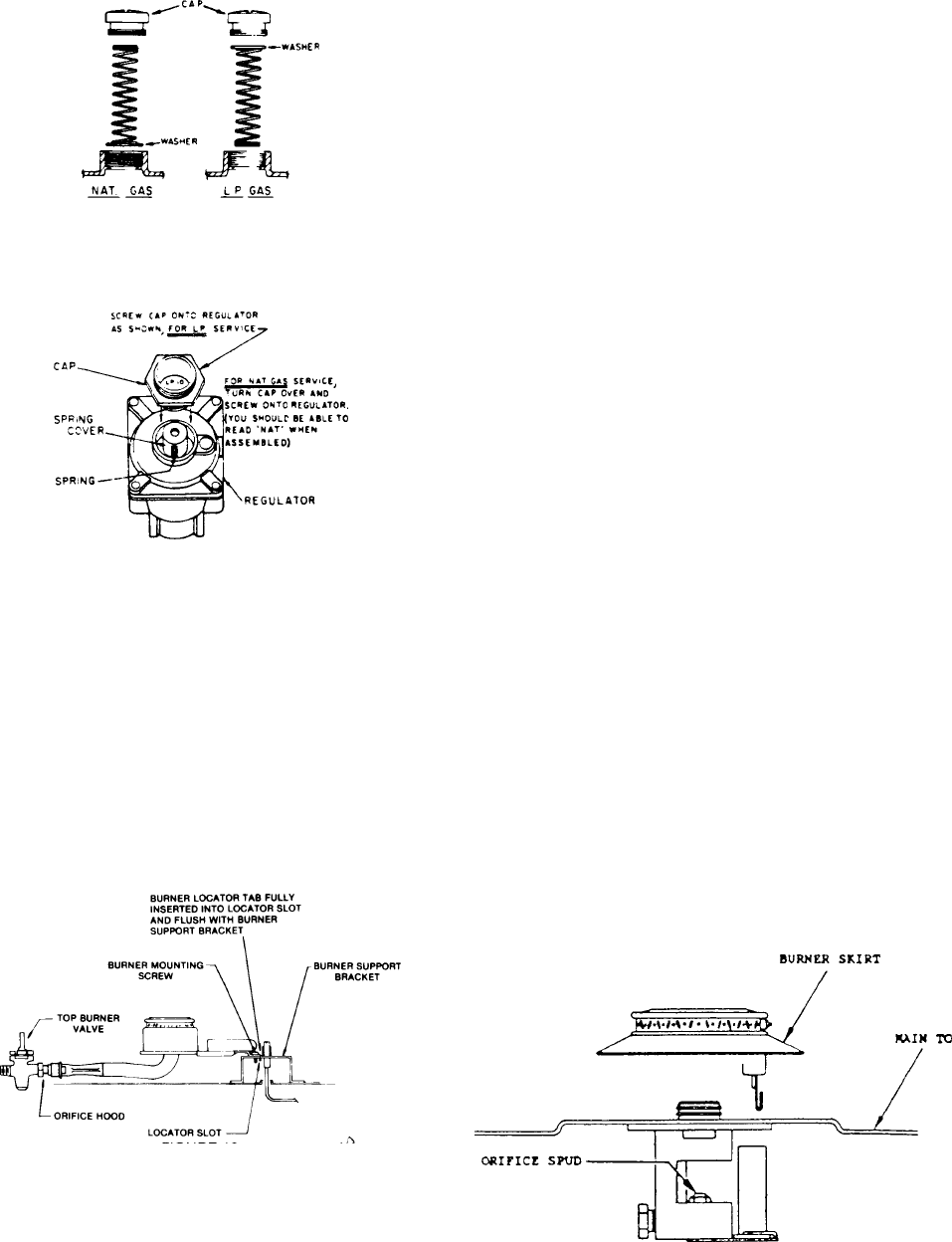
TOP BURNER ADJUSTMENT
ORIFICES
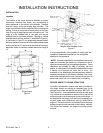
Remove four (4) top burners by removing the mounting
screws and lifting out of bracket. Then turn down the orifice
hoods onto the pins being careful not to drive pin into the
valve or to distort the hole through the center of the pin.
Reinstall the top burners and mounting screws. (See
Figure 15.)
FIGURE 25