


INSTALLATION INSTRUCTIONS
13 RC231002 Rev. 3
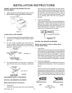
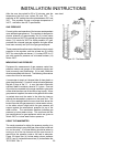
Models with Sealed Top Burners (Above Serial
Number F0430127550)
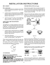
The air shutters (see Figure 6) should be adjusted for a
proper flame. Adjust the air shutter so that the flame has
an inner cone of bluish-green and an outer mantle of dark
blue. The flame should be soft in character. To adjust the
air shutter to close the opening to decrease the air or
enlarge the opening for more air. Tighten the lock screw
when the adjustment is complete.
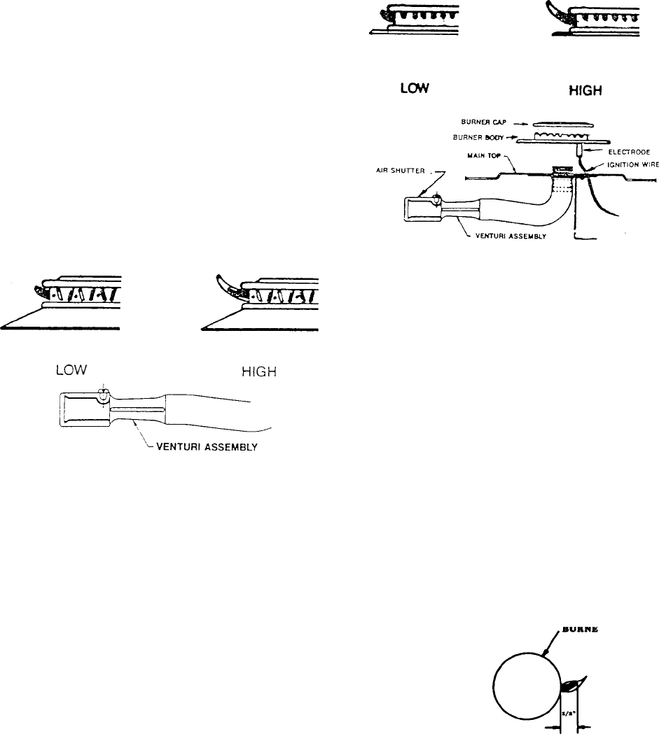
Low burner flame may be adjusted by turning adjustment
screw in center of valve stem. Normally, the low flame
should be adjusted to the minimum steady blue flame
(approximately 1/4" flame length). Check the adjustment
by turning from high to low several times to see that the
burner does not go out.
Figure 16
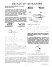
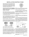
Models with Cast Top Burners
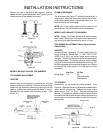
The air shutters (See Figure 7) should be adjusted for a
proper flame. Adjust the air shutter so the flame has an
inner cone of bluish-green and an outer mantle of dark
blue.
For Access to the Air Shutters:
Lift off four (4) burner caps. Remove one (1) screw at each
burner body. Pull each burner body upwards and discon-
nect the ignition wire at the electrode. Remove one (1) flat
headed screw at each burner and lift off main top. Remove
plenum box covers (when so equipped).
To Adjust the Air Shutter:
Loosen the lock screw. Move the air shutter to close the
opening to decrease the air or enlarge the opening for more
air. Tighten the lock screw when the adjustment is com-
plete.
Low burner flame may be adjusted by turning adjustment
screw in center of valve stem. Normally, the low flame
should be adjusted to the minimum steady blue flame
(approximately 1/4" flame length). Check the adjustment
by turning from high to low several times to see that the
burner does not go out. (See Figure 8.)
Figure 17
LOWER OVEN BURNER - RST
The appearance of properly adjusted oven burner flame is
a bluish-green inner cone and a dark blue mantle. The
flame characteristics should be clean and soft with no
yellow tips. Blowing or lifting of the flame should not occur.
1. An electric ignitor is used to light the burner. DO NOT
attempt to insert any object into the opening of the protec-
tive shield surrounding the ignitor coil. Do not attempt to
clean this area.
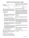
2. The burner flame should be 1/2" long when the air
shutter is correctly adjusted. (See Figure 8.) The air
shutter is located at the lower right of the access area,
above the gas valve. To adjust the air shutter, loosen the
lock screw. Move the air shutter to close the opening to
decrease the air or enlarge the opening for more air.
Tighten the lock screw when the adjustment is complete.
Figure 18
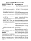
UPPER OVEN BURNER ADJUSTMENT - RST
The burner flames should be 3/8" long when the air shutter
is correctly adjusted. The air shutter is located at the left
side of the upper oven burner. To adjust the air shutter,
loosen the lock screw. Move the air shutter to close the
opening to decrease the air or enlarge the opening to
increase the air. Tighten the lock screw when the adjust-
ment is complete.