


OPERATION AND SERVICE PROCEDURES
(SLIDE IN MODELS)
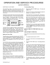
29 RC231002 Rev. 3
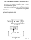
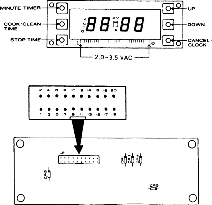
ohmmeter leads to Pins 10 and 17 at the display board
J1 connector and then reversing the ohmmeter leads.
One reading should indicate infinite ohms and the
other reading should indicate low ohms (CR1 diode
conduction resistance). If a zero (0), or infinite ohms
reading is indicated with the meter leads connected in
both directions, the display board should be replaced.
P.C. BOARD/DISPLAY BOARD
INTERCONNECT CABLE
The 20 pin ribbon cable that connects the Clock/Timer P.B.
board to the display board can be checked for continuity
using an ohmmeter set to the low ohms scale. Refer to
Figure 29 and 30 for correct pin identification. If an open
wire is indicated in the ribbon cable, the cable should be
replaced.
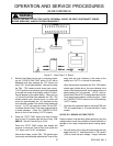
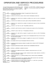
The information on Page 54 pertains to the 20 wire ribbon
cable which connects the P.C. board to the display board.
A switch was added to each wire of the ribbon cable to
demonstrate the results if that switch/wire opened. This
information may be useful in diagnosing and repairing
some display/control problems on the digital clock/timer.
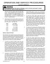
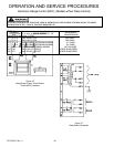
Figure 58 - Display Board
Figure 59 - Display Board - Rear View