INSTALLATION INSTRUCTIONS
11 RC231002 Rev. 3
INSTALLATION INSTRUCTIONS FOR ANTI-TIP
BRACKET
To Install Anti-Tip Bracket, Carefully Follow these
Instructions:
1. Prepare counter cutout per range Installation Instruc-
tions.
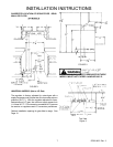
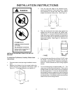
2. Measure the distance from the range leveling leg
shaft to the rear most projection of the range. (See
Figure A). This will be referred to as distance "A".
Figure 7
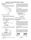
3. From the right rear edge of the prepared cutout,
measure the distance "A" and mark a point. Repeat
this procedure for the left hand side, then draw a
straight line between these points. (See Figure A.)
Figure 8
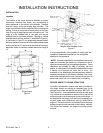
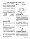
4. Place the bracket with the inside edge against the
straight line and the end against the cabinet side.
(See Figure C.) If you do not have cabinets on both
sides of the range, it will be necessary to measure the
width of the range (W) and place the bracket at the
appropriate location. (See Figure D.) Mark two (2)
hole locations.
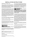
5. If mounting into wood flooring, drill two (2) 3/32" holes
as marked. If mounting into concrete, using a ma-
sonry drill bit, drill two (2) 3/16" holes and insert plastic
anchors. Position bracket and mount using supplied
screws.
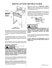
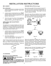
6. Turn the leveling legs out approximately 1/4". The
range may now be pushed into position. Remove the
storage drawer and check that the leg has engaged
the mounting bracket. If it has not, the bracket must
be relocated to ensure engagement of the leveling leg
into the bracket. If the range is moved from its original
mounting location, the bracket must be removed and
used for the new mounting location.
Figure 10
Figure 9


