


OPERATION AND SERVICE PROCEDURES
(SLIDE IN MODELS)
RC231002 Rev. 3 26
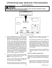
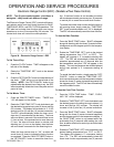
3. Attach the ohmmeter leads to the P.C. board L1 (TB1)
and N (TB2) terminals. A resistance reading of
approximately one hundred (100) ohms should be
indicated. If zero (0) or infinite ohms is indicated, the
P.C. board must be replaced.
4. Attach one (1) meter lead to the transformer ground
terminal and the other meter lead to the L1 (TB1)
terminal. Infinite ohms should be indicated. If zero
(0) or a low ohms reading is indicated, replace the
P.C. board.
5. Remove the meter lead from the L1 (TB1) terminal
and attach it to the N (TB2) terminal. Infinite ohms
should again be indicated. If zero (0) or a low ohms
reading is indicated, replace the P.C. board.
6. Attach the ohmmeter leads to the K1 relay contact
terminals TB4 and TB5. An infinite ohms reading
should be indicated. If a zero (0) or a low ohms
reading is indicated, replace the P.C. board.
7. Attach the ohmmeter leads to the K1 relay contact
terminals TB6 and TB7. Infinite ohms should be
indicated. If a zero (0) or low ohms reading is
indicated, replace the P.C. board.
8. Set the ohmmeter to the RX1 ohms scale and zero the
meter. Attach the meter leads to pins two (2) and
fourteen (14) at the P.C. board J2 20 pin plug block.
A resistance reading of approximately two (2) to three
(3) ohms should be indicated. If an infinite ohms
reading is indicated, replace the P.C. board.
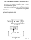
K1 RELAY CONTACT TESTING
1. Shut off power to the range.
2. Remove the wire leads from the P.C. board terminals
TB4, TB5, TB6, and TB7. Wrap the wire lead terminal
ends with electrical tape to reduce the possibility of
electrical shock or a short circuit to the range.
3. Set an ohmmeter to the RX1 scale and connect the
meter leads to P.C. board terminals TB4 and TB5.
4. Turn on the power to the range and set the clock for
the correct time of day. Contact TB4 - TB5 should be
open (infinite ohms).
6. Press the "STOP TIME" button.
7. Press the "UP" button to set the desired stop time of
the self-clean cycle. For example, to have the self-
clean end at 4 o'clock, press and hold the "UP" button
until "4:00" appears on the display, then release the
"UP" button. After approximately five (5) seconds,
the display will revert back to the Time-of-Day and
"AUTO" will appear on the left of the display indicating
the "CLOCK/TIMER" is programmed for an auto-
matic timed operation. The clock will automatically
calculate the start time of the self-clean cycle. In
other words, a three (3) hour self-clean cycle would
begin at one (1) o'clock and end at four (4) o'clock.
When the start time of the self-clean cycle is reached,
the oven indicator in the center of the display will
come on and the clean cycle will begin.
The oven indicator light on the control panel will come
on and cycle ON and OFF with the thermostat. When
the stop time is reached, the oven indicator turns off
and an alarm will sound for approximately ten (10)
seconds. The oven will automatically turn off and
"AUTO" will continue to blink on and off indicating the
Clock/Timer was set for an automatic timed mode
and it is not completed.
8. After the clean cycle turn the selector switch to
"MANUAL", the oven control to "OFF", and press the
"CLOCK/CANCEL" button.
9. The oven door can be opened approximately thirty
(30) minutes after the completion of the clean cycle.
Do not attempt to open the oven door latch until
approximately thirty (30) minutes have elapsed, oth-
erwise the door lock mechanism may be damaged.
DO NOT FORCE THE LATCH HANDLE.
If the oven door will not open, wait five (5) minutes and
try again.
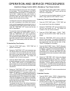
CLOCK/TIMER TESTING PROCEDURES
P.C. BOARD TESTING - NO POWER TO UNIT
1. Shut off power to the range and remove the P.C.
board.
2. Set ohmmeter to RX10 scale.
TO AVOID THE RISK OF ELECTRIC SHOCK, PERSONAL INJURY OR DEATH DISCONNECT POWER
BEFORE SERVICING, UNLESS TESTING REQUIRES IT.