


FIRE OR EXPLOSION - TO AVOID THE RISK OF ELECTRICAL SHOCK, PERSONAL
INJURY, OR DEATH, DISCONNECT POWER TO THE OVEN BEFORE SERVICING.
DISASSEMBLY PROCEDURES - RST MODELS
RC231002 Rev. 3 90
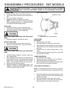
BACKGUARD SUPPORT
1. Shut off power to the unit.
2. Disconnect main gas line from unit. Pull unit away
from wall to gain rear access.
3. Remove eight (8) screws securing rear cover to
range.
4. Remove two (2) screws securing backguard end cap
to support.
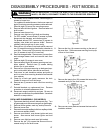
CLOCK OR ERC KNOBS
1. The clock and ERC knobs are removed by pulling
them straight out from the clock or ERC.
VENT TRIM
1. Remove two (2) screws securing vent trim to lower
backguard trim.
BURNER CAPS
Models with Sealed Burners
1. Shut off power to the range. Remove burner grates.
2. Lift burner caps straight up from main top.
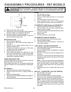
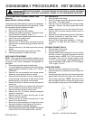
MAIN TOP
Models without Sealed Burners
1. Shut off power to the range.
2. Remove grates and burner bowls (if applicable).
3. Main top is removed by lifting top up in front and then
forward.
MAIN TOP
Models with Sealed Burners
1. Shut off power to the unit.
2. Remove burner grates and burner caps.
3. Remove eight (8) screws securing main top to ven-
turi. Lift main top up and forward to remove.
MAIN TOP TRIM
1. Shut off power to the range.
2. Remove main top and lay top on a protected surface
with top facing downward.
3. Remove two (2) screws and spacers securing trim to
main top and remove trim.
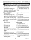
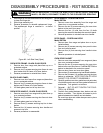
CONTROL PANEL
1. Shut off power to the range.
2. Remove burner grates, burner bowls, and main top.
3. Remove top burner knobs. On models without the
ERC, the thermostat and selector switch knobs must
also be removed. Remove oven door.
4. Remove five (5) screws securing control panel to
front frame filler strip.
5. Remove two (2) screws securing end caps to side
panel. Pull control panel front and then up to remove
from valve stems. Remove filler strip located be-
tween control panel and burner box on models with-
out sealed burners.
6. To remove end caps, remove two (2) screws securing
each end cap to control panel.
7. Remove two (2) screws securing thermostat to con-
trol panel and two (2) screws securing selector switch
to control panel (except ERC models).
On Models RST307 and 309, the indicator lights,
rocker switch, and clock display board mounting
bracket must be removed from the control panel.
OVEN LIGHT SWITCH
Slide In Models
1. Disconnect electricity at main disconnect plug.
2. Remove control panel.
3. Remove wires from terminals on light switch.
4. Gently squeeze clips on switch and push through front
of control panel.
5. Reverse procedure to reinstall new switch.
INDICATOR LIGHT REMOVEAL (OVEN, CLEAN)
Slide In Models
1. Shut off power to the range.
2. Partially remove the control panel. Follow Control
Panel Removal Procedures, Steps 2 - 5.
3. Remove the indicator from the indicator lens by
sliding the indicator spring finger tabs off of the lens.
The indicator lens can now be removed by pushing it
out of the control panel.
4. Disconnect the indicator wire leads.
5. Follow reverse procedures to reinstall the indicator
light.
OVEN-ON/CLEAN INDICATOR LIGHT
1. Disconnect electricity at main disconnect plug.
2. Remove rear cover plate from backguard.
3. Remove screws securing trim (below gackgurard
glass) - remove trim.
4. Support backgurard glass with one hand then remove
clock knobs.
5. Tilt glass out at bottom to clear clock stems.
6. Depress tabs on indicator light and push light assem-
bly through hole in panel.
7. Transfer wires to new indicator light.
8. Reverse procedure to reinstall indicator light.