


FIRE OR EXPLOSION - TO AVOID THE RISK OF ELECTRICAL SHOCK, PERSONAL
INJURY, OR DEATH, DISCONNECT POWER TO THE OVEN BEFORE SERVICING.
DISASSEMBLY PROCEDURES - RST MODELS
RC231002 Rev. 3 92
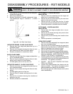
OVEN THERMOSTAT
1. Disconnect electricity at main disconnect plug.
2. Remove oven door and oven racks.
3. Remove burner grates and main top.
4. Remove burner grates and main top.
5. Remove control panel, Steps 3 - 5.
6. Remove burner box.
7. Remove thermostat capillary from shield on the side
of the oven liner.
8. Gently pull capillary lead through the hole in the top
of the oven liner.
9. Remove two (2) screws holding thermostat in place.
10. Transfer wires to new thermostat - one for one (point
to point). Be certain to check wiring diagram to assure
proper wire termination to thermostat.
11. Reverse procedure to reinstall new thermostat. NOTE:
Be certain to check the calibration of the thermostat
per instructions. If the thermostat is a warranty item,
be careful not to damage or kink the capillary tube.
Repack thermostat in original carton.
THE CAPILLARY TUBE OR BULB OF THIS
THERMOSTAT, USED IN THE SELF-CLEAN MODELS,
CONTAINS A MIXTURE OF CAUSTIC NATURE. DO
NOT CUT OR BREAK CAPILLARY TUBE. IF TUBE OR
BULB IS BROKEN, THE MIXTURE IS COMBUSTIBLE
IF IT COMES IN CONTACT WITH MOISTURE AND CAN
BE HARMFUL IF IT COMES IN CONTACT WITH EYES,
SKIN, AND CLOTHING. IF BROKEN, A CRIMP MADE
WITH PLIERS ON EACH SIDE OF THE BREAK WILL
RESEAL THE UNIT. If contacted by skin, REMOVE BY
SCRAPING OFF WITH KNIFE, flush skin and knife with
water.
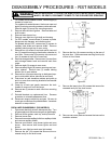
SELECTOR SWITCH
1. Disconnect electricity at main disconnect plug.
2. Remove top burner grates and main top.
3. Remove control panel.
4. Remove two (2) screws securing selector switch to
control panel.
5. Transfer wires to new selector switch - one (1) for one
(1) (point to point).
6. Refer to wiring diagram to assure proper wire termi-
nation.
7. Reverse procedure to reinstall new selector switch.
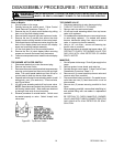
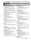
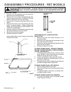
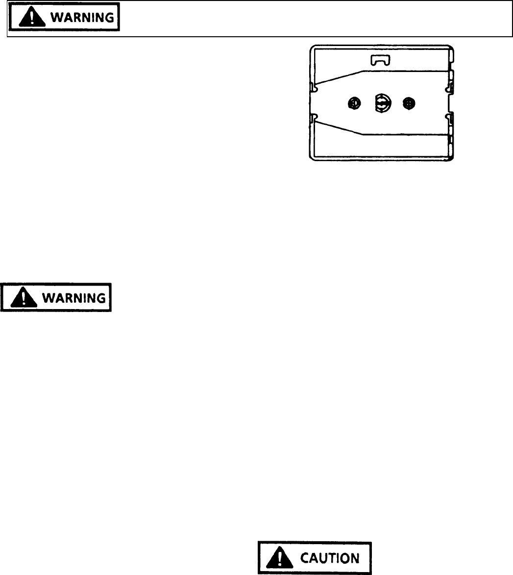
Figure 86 - Front Of Range
Selector Switch Mounting Position
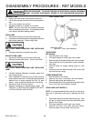
OVEN LATCH SWITCH
1. Disconnect electricity at main disconnect plug.
2. Remove burner grates and main top.
3. Remove two (2) screws securing latch cover to burner
box and remove cover.
4. Disconnect wires to oven latch switch.
5. Remove screws holding switch to bracket.
6. Refer to wiring diagram to assure proper wire termi-
nation.
7. Reverse procedure to reinstall new switch.
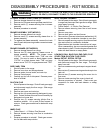
DOOR LATCH ASSEMBLY (RST MODELS)
1. Shut off power to the range.
2. Remove grates, burner bowls, and main top.
3. Remove control panel. Follow Control Panel Disas-
sembly Procedures, Steps 3 - 5.
4. Remove two (2) screws to latch cover.
5. Remove two (2) screws securing latch handle to latch
assembly.
6. Remove two (2) screws securing latch switch mount-
ing bracket to latch assembly.
7. Remove six (6) screws (three (3) each side) securing
burner box to side frames and two (2) screws securing
manifold to burner box. Remove burners. On sealed
burner models, do not remove screws securing mani-
fold to burner box. Remove the two (2) screws
securing manifold to filler trim. Burner box can not be
lifted slightly to gain access to latch assembly.
CARE MUST BE TAKEN TO AVOID BENDING OR
CRIMPING TUBING.
8. Remove screw securing wire clip to insulation re-
tainer.
9. Remove four (4) screws securing latch assembly to
mounting bracket.