


OPERATION AND SERVICE PROCEDURES
Electronic Range Control - ERC - (Models w/One Piece Control)
RC231002 Rev. 3 52
TO AVOID THE RISK OF ELECTRIC SHOCK, PERSONAL INJURY OR DEATH DISCONNECT POWER
BEFORE SERVICING, UNLESS TESTING REQUIRES IT.
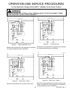
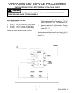
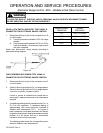
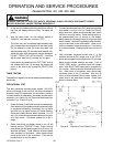
DOOR LATCH SWITCH CIRCUITRY TEST USING J2
CONNECTOR ON ELECTRONIC RANGE CONTROL
1. Disconnect the four (4) pin in-line connector from J2
on circuit board.
A. Continuity should be indicated J2 Pin 3 to range
chassis.
B. Continuity should be indicated J2 Pin 3 to J2 Pin
4 with door latched. No continuity (open circuit)
with door unlatched.
Check door latch switch, wiring integrity according to
appropriate wiring diagram.
Figure 48
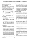
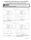
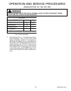
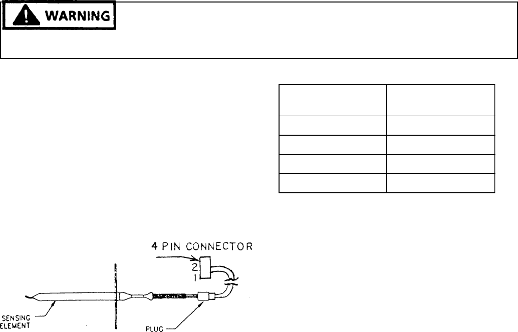
OVEN TEMPERATURE SENSOR TEST USING J2
CONNECTOR ON ELECTRONIC RANGE CONTROL
1. Disconnect the four (4) pin in-line connector from J2
on circuit board.
2. Check for short to ground from Pin 1 to range chassis.
Check for short to ground from Pin 2 to range chassis.
If no short to ground, proceed to Step 3.
If short to ground is indicated then repeat test on
sensor plug - replace oven sensor or wire harness as
required.
3. A resistance reading can be checked across Pin 1 to
Pin 2 of 4 Pin connector. A resistance reading of
approximately 1091 ohms should be indicated at
ambient room temperature (75°F.). If a higher or
lower resistance is indicated disconnect the sensor
plug and recheck sensor resistance to assure that the
problem is in the sensor and not in interconnect
harness or due to a bad connection.
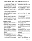
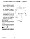
The following table shows the corresponding resis-
tance for different oven temperatures.
SENSING ELEMENT
TEMPERTURE
SENSING
RESISTANCE
75°F 1091 ± 5.5 OHMS
350°F 1654 ± 11 OHMS
535°F 2018 ± 16 OHMS
875°F 2652 ± 24 OHMS