


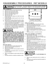
FIRE OR EXPLOSION - TO AVOID THE RISK OF ELECTRICAL SHOCK, PERSONAL
INJURY, OR DEATH, DISCONNECT POWER TO THE OVEN BEFORE SERVICING.
DISASSEMBLY PROCEDURES - RST MODELS
RC231002 Rev. 3 88
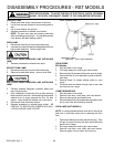
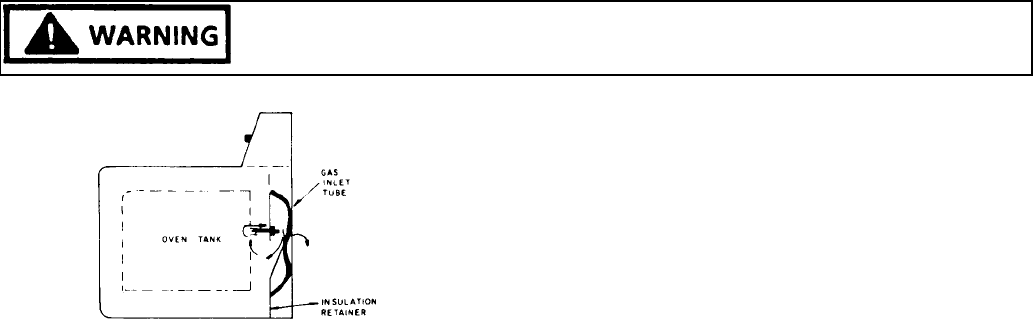
Figure 84
11. Remove rear tank retention clips.
12. Grasp the lip of the oven tank and gently maneuver
the tank forward to free itself from the range.
13. Reverse procedure to reinstall hardware.
14. Reconnect range to electricity and gas. Check main
gas connection with soap suds.
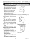
BACKGUARD GLASS
1. Shut off power to the range.
2. Remove clock or ERC knobs by pulling straight out
from glass.
3. Remove two (2) screws securing lower trim to
backguard control panel.
4. Tilt glass out at bottom to clear clock or ERC knobs
and light switch stem (if applicable).
5. Remove glass and lower trim.
6. When replacing the glass on models with an oven
light and/or fluorescent light, the light switch bezel
and retainer clip must be removed from glass and
transferred to replacement glass.
LOWER BACKGUARD TRIM
The lower backguard trim can be replaced by using the
backguard glass removal procedure.
When replacing the lower trim, the backguard heat shield
must be removed from trim and attached to replacement
trim.
ERC REMOVAL
1. Disconnect electricity at main disconnect plug.
2. Remove knobs from ERC by pulling forward on
knobs.
3. Remove backguard glass.
4. Remove four (4) screws and spacers securing ERC to
mounting bracket.
5. Disconnect two (2) wire connectors and remove ERC.
CLOCK
1. Shut off power to range.
2. Remove backguard glass.
3. Remove screws securing clock to the mounting
bracket.
4. Pull clock forward and disconnect wiring.
5. When reinstalling clock, refer to the appropriate
wiring diagram to assure correct wire termination.
FLUORESCENT LAMP (Backguard) (RSS MODELS)
1. Disconnect electricity at main disconnect plug.
2. Remove bottom trim and grille supporting glass.
Remove knobs and glass.
3. Gently twist fluorescent while pulling forward to loosen
end pins in sockets.
4. Remove light.
5. Reverse procedure to reinstall light.
FLUORESCENT LAMP (RST MODELS)
1. Disconnect electricity at main disconnect plug.
2. Remove backguard glass.
3. Fluorescent lamp is now accessible. Twist lamp to
remove from sockets.
LIGHT SWITCH - BACKGUARD MOUNTED
1. Disconnect electricity at main disconnect plug.
2. Remove backguard glass.
3. Remove fluorescent lamp (if applicable) to prevent
damage to lamp.
4. Remove 1/2" nut securing switch to backguard con-
trol panel.
5. Remove four (4) screws (two (2) each side) securing
backguard control panel to end caps and tilt control
panel forward.
NOTE: There is a spacer bracket located between
the control panel and the top trim which will be loose
when the control panel is moved forward. Replace
with angled edge toward back and angle facing
downward.
6. Disconnect wire nuts to switch leads and remove
switch.
BALLAST - FLUORESCENT LIGHT (RST MODELS)
1. Shut off power to the range.
2. Remove backguard glass.
3. Remove fluorescent lamp to prevent damage.
4. Remove four (4) screws securing backguard control
panel to end caps and tilt control panel forward.
NOTE: There is a spacer bracket located between
the control panel and the top trim which will be loose
when the control panel is moved forward. Replace
with angled edge toward back and angle facing
downward.