


FIRE OR EXPLOSION - TO AVOID THE RISK OF ELECTRICAL SHOCK, PERSONAL
INJURY, OR DEATH, DISCONNECT POWER TO THE OVEN BEFORE SERVICING.
DISASSEMBLY PROCEDURES - RST MODELS
89 RC231002 Rev. 3
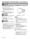
5. Remove two (2) screws securing ballast to control
panel.
6. Disconnect wires to ballast.
BALLAST (RSS MODELS)
1. Disconnect electricity at main disconnect plug.
2. Remove rear coverf plate from backguard.
3. Disconnect leads to terminals on ballast.
4. Remove the two (2) screws securing ballast to
backguard.
5. Reverse procedure to reinstall replacement ballast.
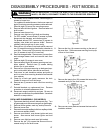
STARTER - FLUORESCENT LIGHT
1. Shut off power to the range.
2. Remove backguard glass.
3. Remove fluorescent lamp to prevent damage.
4. Remove four (4) screws securing backguard control
panel to end caps and tilt control panel forward.
NOTE: There is a spacer bracket located between
the control panel and the top trim which will be loose
when the control panel is moved forward. Replace
with angled edge toward back and angle facing
downward.
5. Push in and turn starter counterclockwise to remove.
STARTER SOCKET
1. Follow Steps 1 - 5 for starter removal.
2. Remove two (2) screws securing starter socket to
backguard control panel.
3. Disconnect wires to start socket and remove socket.
FLUORESCENT LAMP SOCKET
1. Shut off power to the range.
2. Remove backguard glass.
3. Remove fluorescent lamp.
4. Remove four (4) screws securing backguard control
panel to end caps.
NOTE: There is a spacer bracket located between
the control panel and the top trim which will be loose
when the control panel is moved forward. Replace
with angled edge toward back and angle facing
downward.
5. Remove two (2) screws securing lamp socket to
bracket.
6. Cut wire leads at socket and remove socket.
Use lamp socket kit, Part Number 89316, to replace
socket. Kit contains new socket and two (2) terminals.
Strip wire ends and crimp terminals to wires. Snap
terminals into socket.
INDICATOR LIGHT - BACKGUARD MOUNTED
1. Shut off power to the range.
2. Remove backguard glass.
3. Remove four (4) screws securing backguard control
panel to end caps.
NOTE: There is a spacer bracket located between
the control panel and the top trim which will be loose
when the control panel is moved forward. Replace
with angled edge toward back and angle facing
downward.
4. Depress tabs on indicator and remove from control
panel.
5. Disconnect wires to indicator.
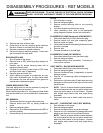
BACKGUARD TOP TRIM
1. Shut off power to the range and disconnect main gas
line.
2. Pull range away from wall to gain rear access.
3. Remove backguard glass.
4. Remove eight (8) screws securing rear cover.
5. Remove two (2) screws securing top trim to end cap.
6. Remove either end cap.
7. Remove center spacer. This spacer is located be-
tween the clock bracket and control panel in the front
and the top trim in back. Angled end is toward the
back and angle faces downward.
8. Remove top trim by gently pulling sideways to disen-
gage trim from remaining end cap.
When reassembling, check main gas connections for
possible leaks.
BACKGUARD END CAP
1. Shut off power to the range. Shut off gas supply and
disconnect main gas line to range.
2. Pull range away from wall to gain rear access.
3. Remove backguard glass.
4. Remove eight (8) screws securing rear cover.
5. Remove two (2) screws securing end cap to control
panel.
6. Remove one (1) screw securing end cap to top trim.
7. Remove two (2) screws securing end cap to backguard
support.
8. Remove end cap by gently pulling sideways to disen-
gage end cap from top trim.
BACKGUARD CONTROL PANEL
1. Shut off power to the range.
2. Remove backguard glass.
3. Remove fluorescent lamp (if applicable).
4. Remove four (4) screws securing control panel to end
caps and tilt control panel forward.
5. Remove components (clock or ERC, indicator light,
fluorescent light components, light switch (es), etc.)
from control panel and assemble them on replace-
ment panel.