


INSTALLATION INSTRUCTIONS
RC231002 Rev. 3 14
BROIL BURNER
Burner Adjustment
1. No gas input adjustment is necessary as the infrared
burner is equipped with a fixed orifice. There is no air
shutter to adjust.
2. An electric ignitor is used to light the burner. DO NOT
attempt to insert any object into the openings of the
protective shield surrounding the ignitor coil. Do not
attempt to clean this area.
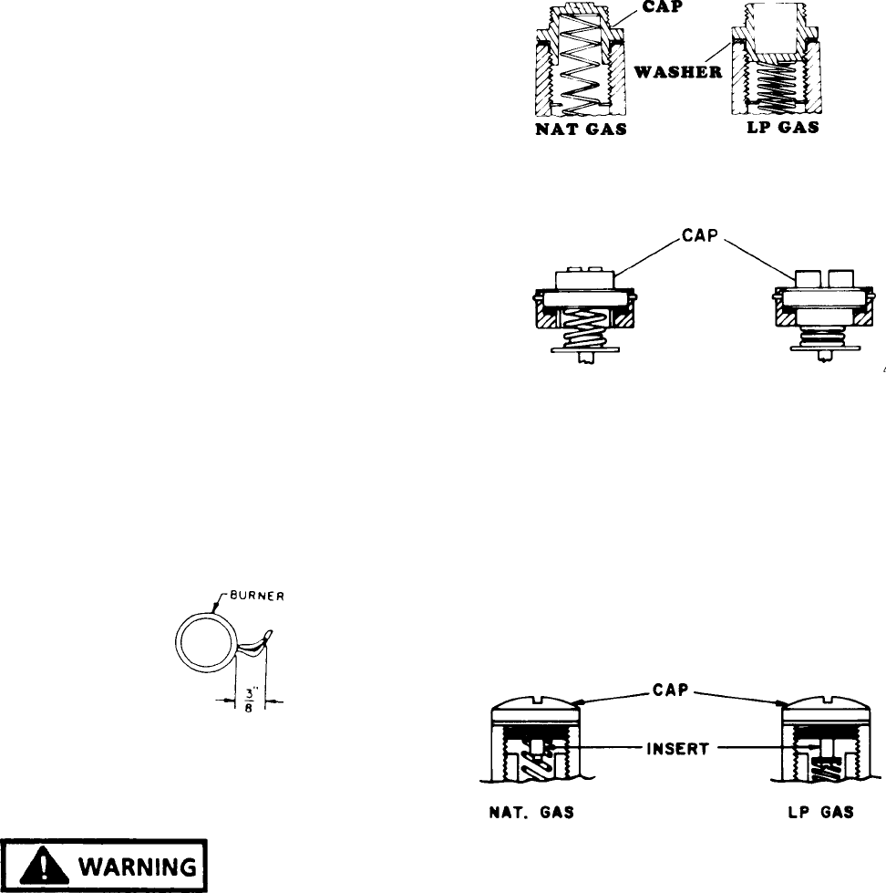
3. The burner may have a hazy or fuzzy appearance
when in operation. This haze may be 3/8" thick
maximum and is normal for this type of burner.
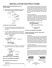
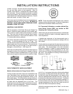
UPPER OVEN FLAME CHARACTERISTIC
ADJUSTMENT
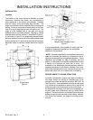
The appearance of a properly adjusted gas flame is one
having an inner cone of bluish-green and an outer mantle
of dark blue. The length of the inner cone flame will be
about 3/8" when correctly adjusted. (See Figure 9.) Flame
characteristics should be clean but soft.
1. An electric ignitor is used to light the burner. DO NOT
attempt to insert any object into the openings of the
protective shield surrounding the ignitor coil. Do not
attempt to clean this area.
2. Oven Burner Adjustment
The burner flame should be 3/8" long when the air
shutter is correctly adjusted. (See Figure 9).
The air shutter is located at the left side of the upper oven
burner. To adjust the air shutter loosen the lock screw.
Move the air shutter to close the opening to decrease the
air or enlarge the opening to increase the air. Tighten the
lock screw when the adjustment is complete.
Figure 19
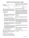
LP CONVERSION
NATURAL TO LP GAS CONVERSION
THIS UNIVERSAL RANGE IS PREADJUSTED FOR
OPERATION ON "NATURAL" GAS AS SHIPPED FROM
THE FACTORY. TO USE THE APPLIANCE ON LP GAS,
YOU MUST DO THE FOLLOWING:
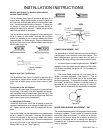
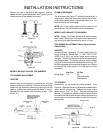
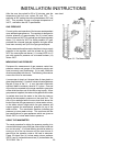
PRESSURE REGULATOR (On Range)
Remove the cap marked "Nat" and reverse it to read "LP".
Be sure not to disturb or remove the spring beneath the
cap. Also make sure the fiber washer is between the cap
and the body of the regulator. See Figure 10 for the
correction position of the cap.
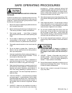
Remove the cap with the screwdriver slot and replace
upside down. This plug will then have the marking "LPG10".
Be sure not to disturb or remove the spring beneath this
plug. See Figure 11 for correct position of plug.
Figure 20
OR
Figure 21
OR
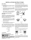
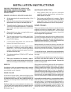
Remove the cap with the screwdriver slot. Remove the
black insert marked "Nat" from the cap. (This is a tight fit
in the cap.) Reverse this insert and carefully push it firmly
into the hole in the cap. The marking "LP" will now be
showing on the insert. Be sure the insert is pressed into the
shoulder. Also, be sure not to disturb the spring in the body
of the regulator.
Replace the cap in the body of the regulator and tighten.
See Figure 12 for the correct position of the insert.
Figure 22
Remove the cap with screwdriver slot. Carefully remove
the spring and washer (washer will be at bottom of spring).
Reverse so that washer is at top of spring and reinstall
spring and washer.
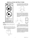
FIRE OR EXPLOSIION
HAZARD