


INSTALLATION INSTRUCTIONS
RC231002 Rev. 3 16
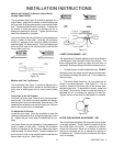
BURNER ADJUSTMENT
No gas input adjustment is necessary as the burner are
equipped with fixed orifices. There are no shutters to
adjust. NOTE: On LP gas a slight yellow tip will be visible
on top burner flames, but will not affect burner perfor-
mance.
OR
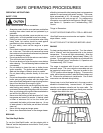
TOP BURNER ADJUSTMENT (Above Serial Number
F0430127550)
TO CONVERT
Lift off four (4) burner caps. (See Figure 27.) Remove one
(1) screw at each burner body. Pull each burner body
upwards and disconnect the ignition wire at the electrode.
Mark wires for identification on reassembly. Remove one
(1) flat headed screw at each burner and lift off main top.
Remove plenum box covers (when equipped). Remove
two (2) screws from each venturi mounting bracket and
remove venturi assemblies.
Turn the orifice hoods onto the pins. The orifices should be
turned snug onto the pins careful not to drive pin into the
valve or distort the hole through the center of the pin.
Reinstall the burner bodies and caps.
The air shutters should be adjusted for a proper flame.
Adjust the air shutter so that the flame has an inner cone
of bluish-green and an outer mantle of dark blue. The
flame should be soft in character. To adjust the air shutter,
loosen the lock screw. Move the air shutter to close the
opening to decrease the air or enlarge the opening for more
air. Tighten the lock screw when the adjustment is com-
plete. Reinstall the plenum box covers, main top and main
top burners in reverse order of removal. NOTE: On LP
gas a slight yellow tip will be visible on top burner
flames, but will not affect burner performance.
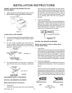
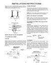
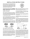
Figure 27
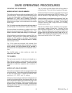
MODELS WITH CAST BURNERS
TO CONVERT
Lift off four (4) burner caps. (See Figure 28.) Remove one
(1) screw at each burner body. Pull each burner body
upwards and disconnect the ignition wire at the electrode.
Remove one (1) flat headed screw at each burner and lift
off main top.
Remove plenum box covers. Remove two (2) screws from
each venturi mounting bracket and remove venturi assem-
blies.
Turn the orifice hoods onto the pins. The orifice should be
turned snug onto the pins careful not to drive pin into the
valve or distort the hole through the center of the pin.
Reinstall the burner bodies and caps.
The air shutters should be adjusted for a proper flame.
Adjust the air shutter so that the flame has an inner cone
of bluish-green and an outer mantle of dark blue. The
flame should be soft in character. To adjust the air shutter,
loosen the lock screw. Move the air shutter to close the
opening to decrease the air or enlarge the opening for more
air. Tighten the lock screw when the adjustment is com-
plete. Reinstall the plenum box covers, main top and main
top burners in reverse order of removal. NOTE: On LP
gas a slight yellow tip will be visible on top burner
flames, but will not affect burner performance.
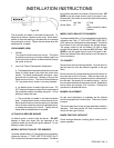
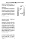
Figure 28
OVEN BURNER (Upper and Lower Oven) (RST)
ORIFICES
Turn down the orifice hood onto the pin. The orifice should
be turned snug onto the pin being careful not to drive pin
into the valve or to distort the hole through the center of the
pin.
LOWER OVEN FLAME CHARACTERISTIC
ADJUSTMENT
The appearance of a properly adjusted oven burner flame
is a bluish-green inner cone and a dark blue mantle. The
flame characteristics should be clean and soft with no
yellow tips. Blowing or lifting of the flame should not occur.
The burner flame should be 1/2" long when the air shutter
is correctly adjusted. (See Figure 18.)
An electric ignitor is used to light the burner. DO NOT
attempt to insert any object into the openings of the
protective shield surrounding the ignitor coil. Do not
attempt to clean this area.