


OPERATION AND SERVICE PROCEDURES
RC231002 Rev. 3 70
TO AVOID THE RISK OF ELECTRICAL SHOCK, PERSONAL INJURY OR DEATH DISCONNECT POWER
BEFORE SERVICING, UNLESS TESTING REQUIRES IT.
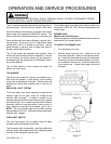
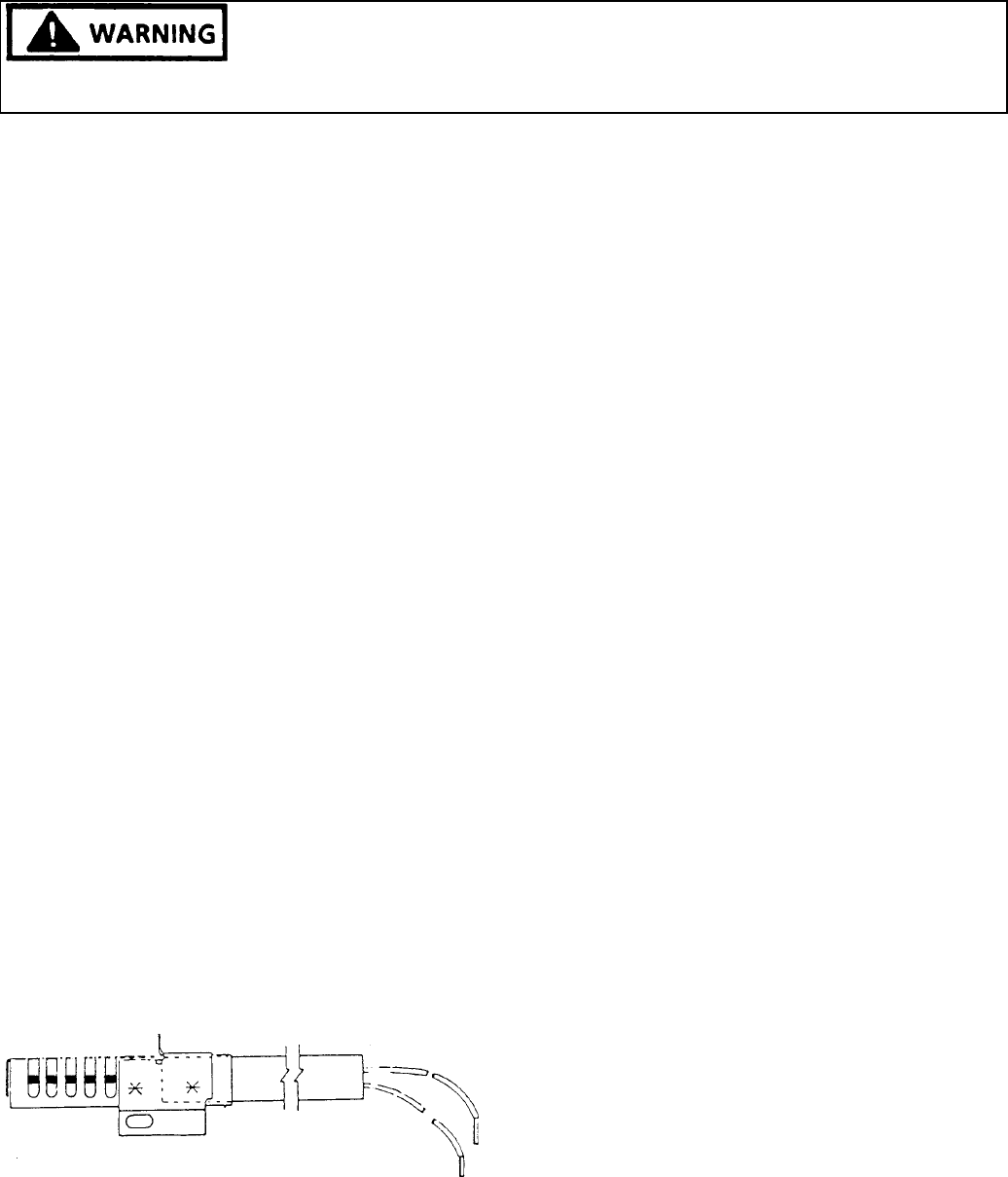
BAKE AND BROIL IGNITORS
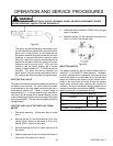
The bake and broil ignitors are mounted to the bake and
broil burners and ignite the gas flowing into the burner.
During a broil or manual bake operation, current flows
through the ignitor, gas valve, selector switch, and thermo-
stat to neutral. As the ignitor starts heating up and glowing,
its internal resistance decreases allowing more current to
flow through the bake or broil circuit. When the circuit
current reaches approximately 3.2 - 3.6 amps, the bi-metal
arm in the gas valve flexes, opening the valve, allowing
gas to flow to the burner where it is ignited by the glowing
ignitor. The ignitors will glow anytime the bake or broil
burners are in operation and cycle on and off with the
thermostat cycling contacts.
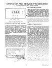
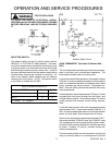
The operation of the OVEN/BROILER "ELECTRIC IGNI-
TOR" can be checked by using a VOLT/OHMMETER as
follows: NOTE: This check must be made while the ignitor
is at ambient room temperature.
1. Disconnect electricity.
2. Set the volt/ohmmeter on the RX1K ohms scale.
(Zero the meter.)
3. Remove ignitor from burner.
4. Remove ignitor lead wire nuts and disconnect ignitor
leads from range wiring.
5. Connect ohmmeter leads to ignitor wire leads.
6. If the meter indicates continuity (a low resistance
reading), the ignitor is operative. NOTE: The cold
ohms. However, this test is for continuity without a
dead short (zero ohms).
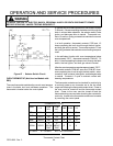
The ignitor may still be defective even though conti-
nuity is indicated and it glows when the oven is set for
bake, broil, or clean function. A more exact test can
be made to measure the ignitor current with the oven
operating. An ammeter should be inserted in series
with one (1) lead of the ignitor or an amprobe can be
attached to the lead to check the amount of current
flowing through the ignitor circuit. With the oven
turned on and the ignitor glowing red, a current
reading of approximately 3.2 - 3.6 amps should be
indicated. The ignitor can also be removed and
bench tested, using the current test method and an
AC jumper or test cord connected to the ignitor leads.
ELECTRIC GAS VALVE
The bake and broil dual gas valve supplies the gas flow to
the bake or broil burners. The valve contains be-metallic
arms attached to the valve seats and are wound with a
small electric heater coil. When a current range of
approximately 3.2 - 3.6 amps flow through the bake or broil
circuit, the bi-metallic arm is heated causing it to flex or
bend, allowing gas to flow to the burner where it is ignited
by the burner ignitor. The gas valve is located behind the
storage drawer.
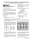
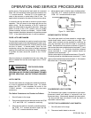
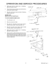
ELECTRIC GAS VALVE TEST WITH VOLT/OHM
METER
1. Disconnect electricity. (Disconnect plug or power
cord.)
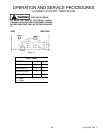
2. Remove the two (2) wire terminals from Point A for
testing "BAKE" portion of gas valve or Point B for
testing "BROIL" portion of gas valve.
3. Set volt/ohmmeter on the RX1 ohms scale (zero (0)
the meter).
4. Attach a meter lead to each of the terminal studs on
the portion of the valve to be tested.
5. If the meter does not show an "OPEN" circuit. The
gas valve is operative.
6. Reattach the two (2) wire terminals removed form
Point A or Point B on the gas valve.