


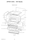
UPPER OVEN - RST Models
RC231002 Rev. 3 102
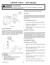
FIRE OR EXPLOSION
TO AVOID THE RISK OF ELECTRICAL SHOCK, PERSONAL INJURY OR DEATH DISCONNECT POWER
BEFORE SERVICING, UNLESS TESTING REQUIRES IT.
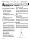
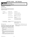
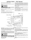
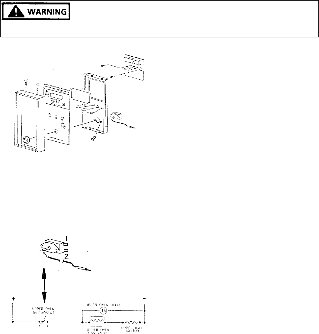
Figure 92
Upper Oven Thermostat
The upper oven thermostat is in series with the upper oven
gas valve, upper oven neon, and upper oven ignitor. When
upper oven is turned from OFF to any temperature selection
contacts 1 and 2 on thermostat close. The oven burner is
turned on as the oven temperature increases.
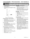
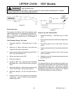
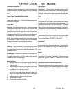
Figure 93
The contacts 1 to L open and close to maintain selected
oven temperature.
Test Procedure:
1. Disconnect electricity.
2. Remove upper oven control panel assembly.
3. With upper oven thermostat:
OFF: No continuity Contacts 1 to 2
ON: Continuity Contacts 1 to 2
Calibration is by adjusting thermostat dial as per Page 91 or
by calibration screw in center of thermostat shaft.
Oven Light
All models designated to have a light in the upper oven will
be equipped with a special high temperature oven light bulb
which is turned on by an oven light switch located on the air
intake panel.
If the oven light will not turn on:
1. Check the oven light bulb and replace if necessary.
2. Check the oven light switch for continuity. If none,
replace the oven light switch.
3. Check all wiring to be sure all leads are correct and
terminals are tight.
Fluorescent Light System
The fluorescent light system uses a starter and a ballast
which are used in conjunction with the fluorescent lamp. To
test the fluorescent lamp, push in on the switch. The lamp
should light and remain on. If it does not light and remain lit,
check the wiring using the diagram in the appropriate portion
of this service manual. Replace by process of elimination
to locate any faulty parts.
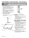
REPLACEMENT OF PARTS
Electric Ignitor: DO NOT DROP
1. Disconnect electricity at main disconnect plug or power
cord.
2. Remove the upper oven control panel, upper oven
bottom, and upper oven racks.
3. Remove the screw securing the ignitor mounting bracket
to the upper oven burner.
4. Disconnect the one "RED" ignitor wire from the electric
gas valve.
5. Disconnect the one "WHITE" ignitor wire from the
white wire junction block.
6. Pull the ignitor assembly into the upper oven.
7. Reverse procedure to reinstall the ignitor assembly.