


FIRE OR EXPLOSION - TO AVOID THE RISK OF ELECTRICAL SHOCK, PERSONAL
INJURY, OR DEATH, DISCONNECT POWER TO THE OVEN BEFORE SERVICING.
DISASSEMBLY PROCEDURES - RST MODELS
93 RC231002 Rev. 3
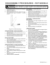
10. Open oven door and remove four (4) screws securing
latch assembly to front frame. Latch assembly can
now be removed.
When replacing latch assembly latch switch and
mounting bracket should be mounted on new latch
assembly.
Be sure there is no insulation in latch hole. When
reinstalling latch cover, be sure louvers are facing the
rear of the range.
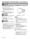
DOOR LATCH ASSEMBLY (RSS MODELS)
1. Disconnect electricity at main disconnect plug.
2. Remove burner grates and main top.
3. Remove control panel and burener box.
4. Disconnect wires to oven latch switch and removee
latch switch.
5. Remove the four (4) screws on the front frame holding
the latch bracket in place.
6. Remove the four (4) screws holding the latch assem-
bly to the latch bracket.
7. Remove latch handle and gently pull out assembly.
8. Reverse procedure to reinstall latch assembly.
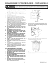
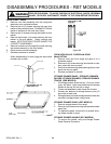
BURNER BOX
Models without Sealed Burners
1. Shut off power to the range.
2. Remove grates, burner bowls, and main top.
3. Remove top burners.
4. Remove eight (8) screws securing burner box to side
panels and manifold.
5. To replace the burner box, remove two (2) screws to
each top burner mounting bracket, disconnect ignitor
lead from spark module, remove latch plate, and
reassemble on new burner box. Reattach ignitor lead
to spark module.
TOP BURNERS
Models without Sealed Burners
1. Shut off power to the range.
2. Remove burner grates, burner bowls, and main top.
3. Remove shipping screw securing top burner to mount-
ing bracket.
4. Twist burner slight to disengage from mounting bracket
and pull burner toward rear of range.
When reassembling, be sure venturi tube is located
properly on burner valve.
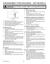
MOUNTING BRACKET - TOP BURNER
Models without Sealed Burners
1. Shut off power to the range.
2. Remove grates, burner bowls, and main top.
3. Remove two (2) screws securing mounting bracket to
the burner box.
4. Remove burner box.
5. Disconnect ignitor lead from spark module.
6. Remove ignitor lead retaining clip and grounding
strap. Remove ignitor lead from bracket.
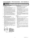
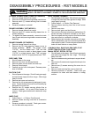
IGNITOR GROUNDING BRACKET
Models without Sealed Burners
1. Shut off power to the range.
2. Remove grates, burner bowls, and main top.
3. Remove top burners.
4. Remove two (2) screws securing the top burner
mounting support to the burner box.
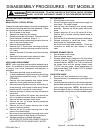
5. Straighten tabs on the ignitor grounding bracket and
remove bracket from the top burner mounting sup-
port. NOTE: Be certain the ignitor grounding bracket
is tight on the top burner support. Also, be sure the
gap between the ignitor grounding bracket dimple
and top of ignitor is 1/8" (-1/32", + 0").
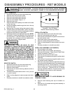
TOP BURNER IGNITOR (RST MODELS)
Models without Sealed Burners
1. Shut off power to the range.
2. Remove burner grates, burner bowls, and main top.
3. Remove top burners.
4. Remove burner box.
5. Disconnect high voltage ignitor leads from spark
module.
6. Remove two (2) screws securing the top burner
mounting support to the burner box.
7. Straighten tabs on the ignitor grounding bracket and
remove bracket from the top burner mounting sup-
port.
8. Remove speed clip securing the spark ignitor to the
top burner mounting bracket. (Clip must be reused,
do not break.)
9. Reverse procedure to reinstall new top burner ignitor.
NOTE: Be certain the ignitor grounding bracket is
tight on the top burner support. Also, be sure the gap
between the ignitor grounding bracket dimple and top
of ignitor is 1/8" (-1/32", + 0").