


OPERATION AND SERVICE PROCEDURES
73 RC231002 Rev. 3
ignition circuit. One terminal of each switch is connected
to the 120 VAC line while the other terminal connects to the
"L1" module terminal. Terminal "N" of the module con-
nects to the common or neutral side of the AC line. The
spark switch is located on the stem of the top burner valve.
A continuity test can be made to check for proper switch
operation. Shut off power to the range and remove the
switch wiring. Set an ohmmeter to the RX1 scale and
attach the meter leads to the switch terminals. When the
switch is turned to the "LITE" position, zero (0) OHMS
(closed contacts) should be indicated. Infinite OHMS
(open contacts) should be indicated in all positions except
"LITE". If the switch fails this test, it must be replaced.
DOOR LATCH MECHANISM
The door latch mechanism is used to insure the oven door
is sealed tightly against the chassis during the clean cycle.
The latch cannot be moved to the "CLEAN" position unless
the door is closed. A thermal safety "jams" the lock
mechanism during the clean cycle to prevent accidental
opening of the door latch during cleaning. When the latch
is jammed the latch cannot be moved to the "COOK"
position.
After the cleaning is completed and the oven cools, the
latch is released and can be moved again to the "COOK"
position.
FIRE OR EXPLOSION
TO AVOID THE RISK OF ELECTRICAL SHOCK,
PERSONAL INJURY OR DEATH DISCONNECT POWER
BEFORE SERVICING, UNLESS TESTING REQUIRES
IT.
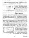
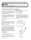
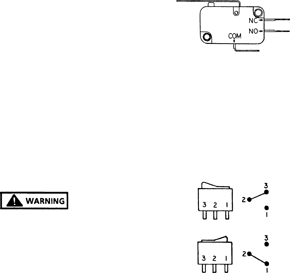
LATCH SWITCH
The door latch switch is a single pole, double throw switch.
It is used to complete the self-clean cycle. On models
without the ERC, it also completes the circuit to the
"CLEAN" indicator. It is mounted on the door latch
mechanism.
The Switch Contacts can be Checked as Follows:
1. Shut off power to the range.
2. Disconnect the switch wire leads and check the COM
- N.O. and COM - N.C. contacts for continuity.
3. When the door latch is in the left or unlocked position,
the COM - N.O. contacts should be open and the
COM - N.C. contacts should be closed.
4. Move the door latch to the far right or locked position.
The COM - N.O. contacts should be closed and the
COM - N.C. contacts should be open.
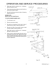
Figure 74 - Latch Switch
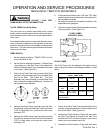
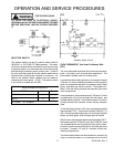
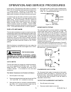
ROCKER SWITCH TESTING
The rocker type switch on these models is a single pole,
double throw switch used to control the oven light. The
rocker switch contacts can be checked for continuity by
using an ohmmeter set to the RX1 scale or a continuity
tester. Set the switch to the position as shown in Figure 31
and connect the meter or tester leads to terminals 2 - 3 and
then to terminals 1 - 2. Continuity should be indicated
across terminals 2 - 3 and open contacts should be
indicated across terminals 1 - 2.
Set the rocker switch to the position as shown in Figure 32.
Continuity should be indicated across terminals 1 - 2 and
open contacts indicated across terminals 2 - 3. If the switch
fails either test, it should be replaced.
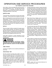
Figure 75
Figure 75A
FLUORESCENT LIGHT SYSTEM
The fluorescent light system incorporates a light switch,
fluorescent starter and ballast in conjunction with the
fluorescent lamp. Momentarily depress the lamp switch.
The lamp should light and remain lit until the switch is
depressed a second time.
TO TEST THE FLUORESCENT LIGHT SWITCH
1. Shut off power to the range.
2. Disconnect switch leads to wire nuts.