


OPERATION AND SERVICE PROCEDURES
Electronic Range Control (ERC) (Models w/ Two Piece Control)
35 RC231002 Rev. 3
TO AVOID THE RISK OF ELECTRIC SHOCK, PERSONAL INJURY OR DEATH DISCONNECT POWER
BEFORE SERVICING, UNLESS TESTING REQUIRES IT.
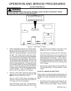
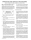
ERC SYSTEM EXPLANATION
THE ELECTRONIC RANGE CONTROL - ERC - operates
in conjunction with a remote relay/power supply circuit
board and an oven temperature sensor to control all bake,
timed bake, broil, and self-clean functions.
The ERC has eight (8) function buttons to control minute
timer, clock, stop time, bake, timed bake, broil, clean and
set/cancel operations, and a rotary dial to set time and
temperature.
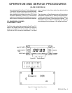
The ERC display consists of two (2) digital readouts which
display the time of day, cooking time, cleaning time,
minute timer time, stop time, baking temperature, lo/hi
broil and failure codes as well as several indicators to show
which function the ERC is controlling.
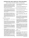
The relay/power supply circuit board consists of two (2)
relays for bake and broil operations which are controlled by
the ERC, and a step down transformer with two (2) second-
ary windings which convert the 120 VAC input to 3.2 VAC
filament voltage to power the ERC display and 20.3 VAC
drive voltage which the ERC uses to turn on the bake and
broil relays.
The oven temperature sensor is mounted in the oven
cavity and is connected to the J2 connector on the rear of
the ERC. As the oven temperature increases, the sensor
resistance also increases. The ERC converts this resis-
tance change to a corresponding temperature readout.
The ERC then cycles the bake/broil relays to maintain the
desired temperature setting.
The ERC is also capable of sensing certain failure condi-
tions which can occur in the temperature sensor, the self-
clean latch switch or the ERC itself. If the ERC senses a
failure, power will be removed from the bake/broil relays,
an alarm will sound, and a failure code will be displayed.
Each major component of the Electric Range Control
System (ERC, temperature sensor, or relay/power supply
circuit board) is serviced as a separate part. However,
each component and related wire harness must be tested
prior to replacing an individual component.
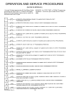
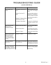
TESTING PROCEDURES
"DISPLAY" MODE - All segments of the display can be
checked by using the following sequence:
NOTE: Clock must previously be set for the time of day.
1. Press and hold the "CLOCK" button until "TIME" is
displayed and until "TIME" turns off.
2. Momentarily press "CANCEL" button until all display
segments are lit. Following the lighting of all of the
segments, the display will go through a "SALES
DEMONSTRATION" mode, displaying individual func-
tions. The "SALES DEMONSTRATION" mode will
show: (1) "BROIL", three (3) horizontal segments and
the degree symbol, (2) "OVEN" "TIME" and ":00" , (3)
"CLEAN", "TIME" and "3:00" (4) "TIMER" and ":00",
(5) time of day, (6) all segments, and (7) "BAKE",
three (3) horizontal segments and the degree symbol.
The program will continue to repeat until the "CAN-
CEL" button is pressed. The time of day should then
be displayed.
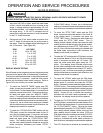
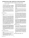
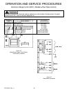
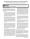
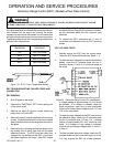
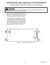
RELAY/POWER SUPPLY CIRCUIT BOARD TESTING
Testing with No Voltage Applied
The relay/power supply circuit board transformer windings,
relay windings, and relay contacts can be checked as
follows:
1. Shut off power to the appliance.
2. Disconnect the J1 connector from the circuit board.
Also remove the wire leads from the circuit board
terminals E1 through E7. Using an ohmmeter, check
for the following readings in Table 1 below. Refer to
Figure 22 for correct terminal/pin location. Figure 23
shows the relay/power supply circuit board sche-
matic.