


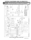
UPPER OVEN - RST Models
103 RC231002 Rev. 3
FIRE OR EXPLOSION
TO AVOID THE RISK OF ELECTRICAL SHOCK, PERSONAL INJURY OR DEATH DISCONNECT POWER
BEFORE SERVICING, UNLESS TESTING REQUIRES IT.
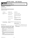
Upper Oven Electric Gas Valve
1. Disconnect electricity at main disconnect plug or power
cord.
2. Remove the upper oven control panel, upper oven
bottom, and upper oven racks.
3. Remove splash plate.
4. Turn off gas at SHUT OFF VALVE behind splash plate
OR turn off gas at supply line to range.
5. Disconnect the "RED" and "WHITE" wires from the
electric gas valve.
6. Disconnect the inlet tubing at the top of the shut off
valve behind the backsplash.
7. Disconnect outlet tubing at the orifice fitting connec-
tion.
8. Remove the two (2) 5/16" nuts from the bolts which
secure the electric gas valve to the rear panel of the
upper oven.
9. Remove the electric gas valve assembly with both
tubings attached. Transfer the tubing to the new gas
valve. Double wrench the fittings to avoid damage.
10. Reverse procedure to reinstall the electric gas valve.
11. Check all gas connections with soap for gas leak.
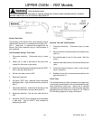
Upper Oven Thermostat
1. Disconnect electricity at main disconnect plug or power
cord.
2. Remove the upper oven control panel. Remove
control panel frame, clock knobs, thermostat knob,
and control panel glass.
3. Disconnect all wires from the thermostat contacts.
Remove the two (2) screws securing the thermostat to
the thermostat mounting plate.
4. Remove the oven thermostat capillary bulb from the
mounting clips in the top of the oven.
5. Reverse procedure to reinstall the upper oven thermo-
stat. Be certain the capillary mounting clips are
positioned properly. Refer to the wiring diagram for
correct wire termination.
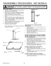
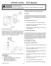
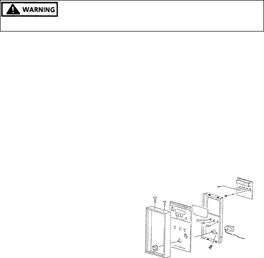
Upper Oven Clock Timer, Indicator Lights, Control
Panel Glass
1. Disconnect electricity at main disconnect plug or power
cord.
2. Remove screws securing control panel frame to con-
trol panel.
3. Remove clock knobs, and oven thermostat knob.
4. Remove control panel glass.
5. Remove screws securing control panel to range frame.
6. Depress tabs and push indicator lights through control
panel. Disconnect wires from indicator light.
7. Remove screws securing clock timer assembly to
control panel. Transfer wires, one (1) for one (1) - point
to point, to new clock timer.
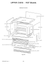
Figure 94