


INSTALLATION INSTRUCTIONS
RC231002 Rev. 3 12
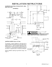
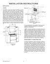
CABINET INSTALLATION OPENING FOR GAS
SLIDE-IN RANGE
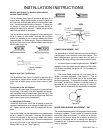
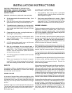
A. Cabinet cutout must be prepared as shown in Figure
11. Never install a range over kitchen carpeting.
Figure 11
LO BACK RAIL SLIDE-IN MODEL
B. For electric and gas connection specifications refer to
instructions for installing automatic pilotless ignition
gas range.
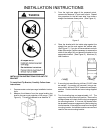
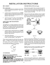
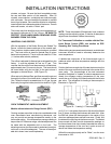
C. On post formed (moulded) tops, shave the front
corner of cabinet opening flush with countertop in
area which will be underneath front corners of range
top (3/8"). (See Figure 12.)
Figure 12
D. On countertops with front metal trim, cut metal trim
back 3/8" from front corner of opening. (See Figure
--.)
ADJUSTMENTS AND LP CONVERSION
NATURAL GAS BURNER ADJUSTMENT
Models Without Sealed Top Burners
1. Top Burners
Whenever a top burner gas valve knob is depressed
and turned fully counterclockwise, the electrode be-
tween the flash tubes will start sparking and continue
as long as the knob is held in this position. After the
burner ignites, move the knob to the "ON" position of
the valve. At this time the sparking will cease. There
are no standing pilots that have to be lighted or
adjusted.
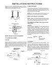
2. Top Burner Adjustment
The air shutter (see Figure 5) should be adjusted to a
proper flame. Loosen the air shutter lock screw and
adjust the air shutter so the flame has an inner cone
of bluish-green and an outer mantle of dark blue. The
flame should be soft in character. Tighten the lock
screw when the adjustment is complete.
Figure 14
NATURAL GAS BURNER ADJUSTMENT
Models with Sealed Top Burners (Below Serial
Number F0430127550)
1. Top Burners
Whenever a top burner gas valve knob is depressed
and turned fully counterclockwise, the electrode built
into the burner cap will start sparking and continue as
long as the knob is held in this position. After the
burner lights, move the knob to the "HI" position of the
valve. At this time the sparking will cease. There are
no standing pilots that have to be lighted or adjusted.
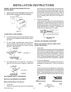
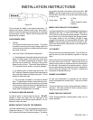
2. Top Burner Adjustment
No gas input adjustment is necessary as the burner is
equipped with a fixed orifice. There is no shutter to
adjust.
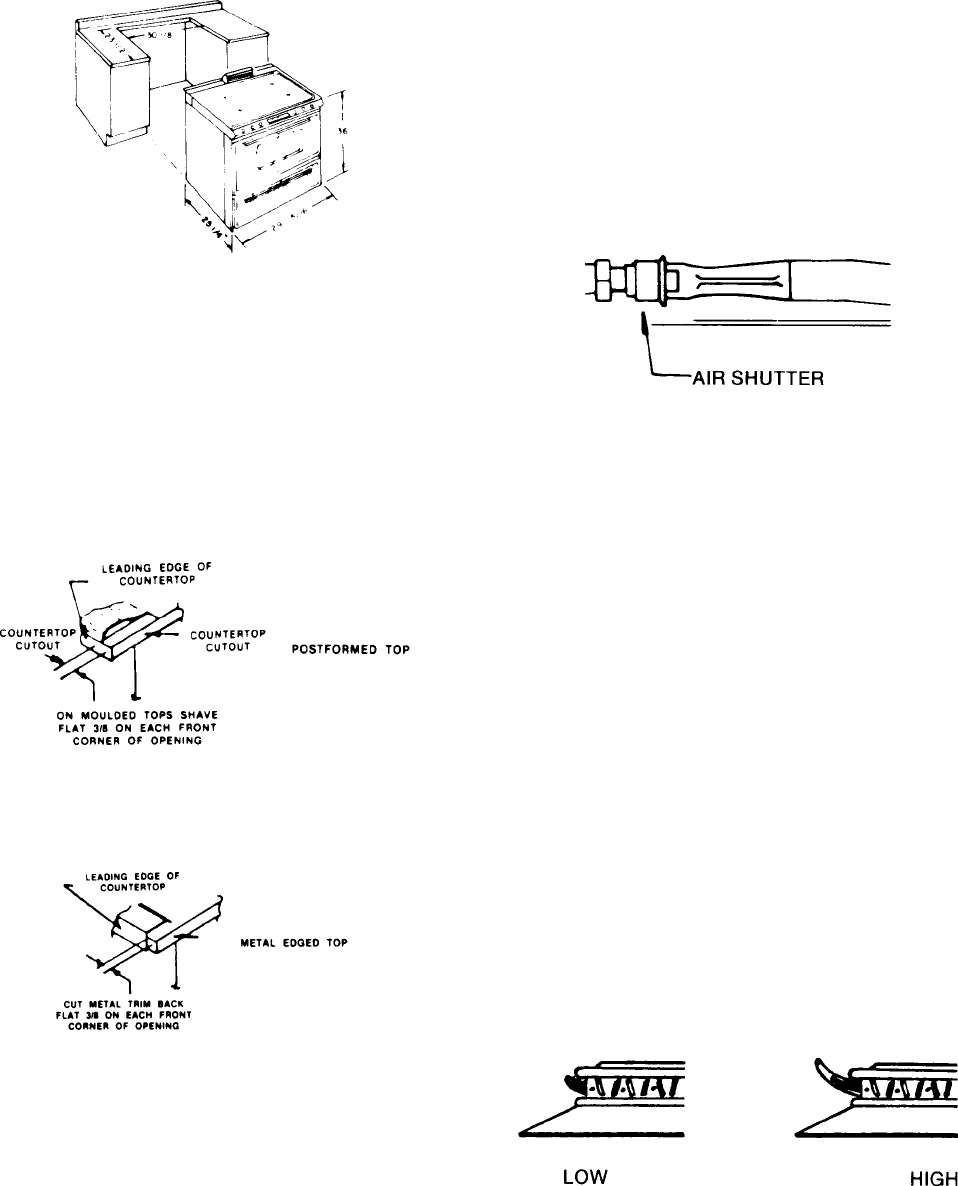
Low burner flame may be adjusted by turning adjust-
ment screw in center of valve stem. Normally, the low
flame should be adjusted to the minimum steady blue
flame. Check the adjustment by turning from high to
low several times to see that the burner does not go
out.
Figure 15
Top Burner Setting
OR
Figure 13