


10 Chiller System Design and Control SYS-APM001-EN
Primary System Components
pumped all the time; however, in systems with very small water pressure
drops, this system arrangement may work economically.
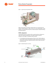
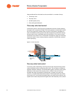
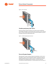
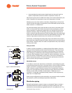
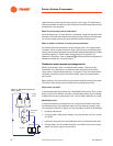
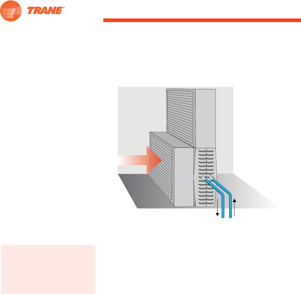
Figure 8. Uncontrolled water flow with bypass damper
Chilled-Water Distribution System
Chilled water is circulated through fixed piping—most commonly steel,
copper, or plastic—that connects the chiller with various load terminals.
Piping is sized to meet pressure loss, water velocity, and construction cost
parameters.
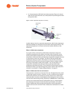
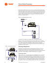
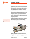
Chilled-water pump
The chilled-water pump creates pressure to circulate chilled water within the
loop. Generally, the pump must overcome the frictional pressure losses
caused by the piping, coils, and chiller and the pressure differential across
open control valves in the system. The pump, while working at the system
static pressure, does not need to overcome this static pressure. For example,
in a forty-story building, the pump need not overcome the static pressure due
to those forty stories.
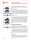
The chilled-water pump is typically located upstream of the chiller; however,
it may be anywhere in the system, provided that the pump:
• meets the minimum pump net positive suction-head requirements. That
is, the system pressure at the pump inlet must be both positive and high
enough to allow the pump to operate properly;
• maintains the minimum dynamic pressure head at critical system
components (usually the chiller). If the dynamic pressure head is not high
enough at these components, proper flow will not be established through
them;
Bypass
Damper
Face
Damper
Airflow
Additional reference information on the
components of a chilled-water
distribution system is available in the
2008 ASHRAE HVAC Systems and
Equipment Handbook, chapter 12,
“Hydronic Heating and Cooling System
Design.”
3