


System Configurations
SYS-APM001-EN Chiller System Design and Control 63
• Locate a bypass line and valve near the end of the piping run. The bypass
control valve sees a lower operating pressure and may provide more
stable control. Some operating cost savings may be sacrificed to maintain
the pump-operating pressure at a higher level with the bypass located
away from the chillers. The line sizes must be large enough to allow the
minimum flow rate.
One final method to ensure minimum evaporator flow is to have a constant
load and flow somewhere in the system. However, if in the future the system
changes and this constant flow no longer occurs, the system is likely to have
operating issues when its flow approaches the chiller’s minimum.
Delivering the appropriate bypass flow requires attention to line sizing,
control-valve selection, and the response time of the system.
Bypass flow control
In a VPF system, the sole purpose of the bypass line with modulating control
valve is to assure that the rate of chilled water flow through each operating
chiller never falls below the minimum limit required by the manufacturer.
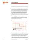
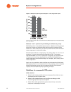
Select a suitable control valve of high quality. When the bypass line is
positioned near the chiller plant (A in Figure 37), as it is in many VPF
installations, the control valve is exposed to comparatively high operating
pressures. Selecting an appropriate valve actuator is critical because the
valve must close against this pressure. As for the valve itself, choose one that
maintains a linear relationship between valve position and flow rate;
otherwise, the valve may permit too much water flow when it begins to open.
Note: A common butterfly valve won’t provide the necessary flow
characteristics. Some have found that pressure-independent valves work well
as a bypass valve. Verify the suitability of a particular valve by requesting
flow-versus-position data from the supplier.
Locating the bypass line far from the chiller plant (B in Figure 37) lowers the
operating pressure for the control valve.
Minimize control lag. Regardless of where the bypass line is situated (at A or
B in Figure 37), the control valve must react quickly to changes in system
flow. You can improve control response either by hard-wiring the flow-
sensing device, valve controller, and valve actuator; or by selecting devices
that communicate directly with each other. Avoid relaying input/output
signals through multiple system controllers.
Chiller sequencing in VPF systems
The success of a VPF application depends on more than the chilled-water
system. It requires careful orchestration of the entire HVAC system, which
means air handlers and coil-control valves as well as chillers and pumps.
Proper sequencing helps to maintain the flow rate through each evaporator
within the range recommended by the chiller manufacturer. As the system