


Primary System Components
SYS-APM001-EN Chiller System Design and Control 11
• accommodates the total pressure (static head plus dynamic head) on
system components such as the chiller’s evaporator, valves, etc.
Note that the pump heat is added to the water and must be absorbed by the
chiller. Generally, this represents a very small temperature increase.
Multiple pumps are often used for redundancy. Depending on the terminal
control devices and system configurations, the chilled-water pumps may be
either constant- or variable-flow.
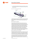
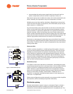
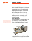
As previously stated, pumps may be either on the inlet or the outlet of the
chiller, as long as the inlet of the pump experiences an adequate, positive
suction pressure. In applications where there is a significant liquid column
head (for example, a high-rise building), the pump is often located at the
chiller’s outlet so that the evaporator bundle is subject only to the static head
(rather than the static head plus the dynamic head added by the pump). The
need for high-pressure water boxes on the chiller can be eliminated.
Conversely, an advantage of locating the pump at the chiller’s inlet is that if
the pump motor rejects its heat to the water, the heat can be removed directly
by the chiller. The chiller does not need to compensate for the pump heat by
making colder water.
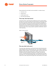
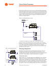
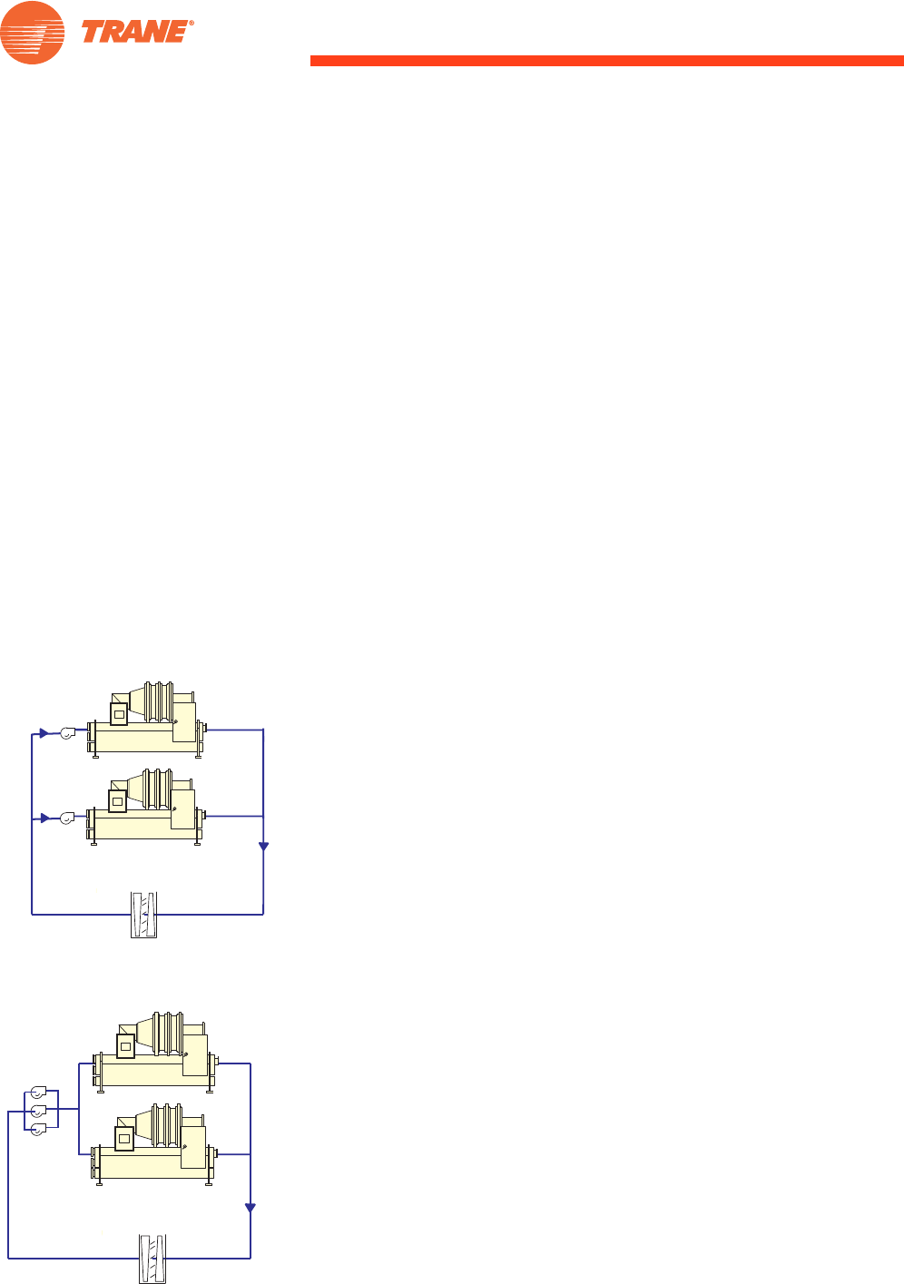
Pump per chiller
In either a primary–secondary or variable-primary-flow system, using one
pump per chiller simplifies system hydraulics (Figure 9). The pump can be
selected to produce the flow and pressure drop necessary for the specific
chiller. Bringing on additional pumps changes system hydraulics, but only
minimally. One drawback of such a system is a lack of redundancy, since the
pump and chiller are dedicated to one another. This may be overcome by
using a spare pump, pipes, and valves so that the spare pump could work
with any chiller during emergency conditions.
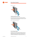
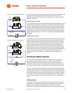
Manifolded pumps
In an effort to resolve the redundancy consideration, some designers prefer
to manifold pumps and provide n+1 pumps, where n is the number of chillers
(Figure 10). Such an arrangement allows any pump to be used with any
chiller. However, system hydraulics become more complicated. Unless all
piping runs and evaporator pressure drops are equal, the amount of water
flowing to each chiller will differ. As discussed in “Moderate ’low T
syndrome’" on page 68, manifolded pumps present a control opportunity
when low T is experienced.
Either pump configuration can be successful; one pump per chiller simplifies
the hydraulics, while manifolded pumps allow redundancy.
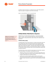
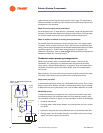
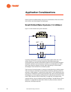
Distribution piping
By itself, the distribution system is easy to understand. Figure 11 shows a
simplified distribution system consisting of multiple cooling coils, each
controlled by a thermostat that regulates the flow in its respective coil. The
Figure 9. Pump per chiller
Load
Pump
Pump
Figure 10. Manifolded pumps
Manifolded
Pumps
Load