


52 Chiller System Design and Control SYS-APM001-EN
System Configurations
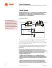
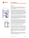
Chiller sequencing in decoupled systems
Given the amount and direction of flow in the bypass line, chillers can be
added or subtracted.
Adding a chiller
When there is deficit flow in the bypass line, the system is receiving water at
a temperature above the desired supply water temperature. At this point in
time, a chiller and pump may be added. Many operators sense deficit flow for
a particular amount of time (for example, 15 minutes) to ensure that the
deficit flow is not a result of some transient condition. This reduces the
chances of cycling a chiller; that is, turning on a chiller and then turning it off
after a short time.
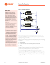
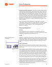
Subtracting a chiller
A chiller may be turned off when enough surplus water is flowing through the
bypass line. How much is enough? Enough so that the chiller does not need
to cycle on again in a short time period. Many system operators compare the
amount of surplus flow with the flow rate of the chiller they are considering
turning off. If this ratio is 110 to 115 percent, they turn the chiller off. Let’s look
at an example:
Chiller 1 can make 960 gpm [60.6 L/s] of 40°F [4.4°C] chilled-water, while
Chiller 2 can make 1,440 gpm [90.8 L/s]. At present, there is 1,100 gpm
[69.4 L/s] of surplus flow in the bypass line.
• The surplus bypass flow is presently 115 percent of Chiller 1’s flow. If we
turn Chiller 1 off, we will have 140 gpm [8.8 L/s] of surplus flow left.
• Note that the surplus bypass flow is presently only 76 percent of Chiller
2’s flow. If we turn Chiller 2 off, we will have 340 gpm [21.5 L/s] of deficit
flow. It is clear that we would have to cycle that chiller back on soon.
In this case, we could turn Chiller 1 off and leave Chiller 2 on for the most
efficient use of the chillers.
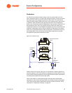
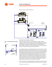
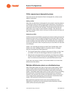
Multiple chilled-water plants on a distribution loop
When decoupled systems are used on large campus-type systems, added
loads are often located some distance away from the original loads. Yet,
planners like the idea of somehow hooking the new loads to the existing
system. The double-ended system shown in Figure 36 is one way of handling
this requirement. A second production facility is placed at a convenient
location in the new part of the campus. Its distribution plant is laid out as a
mirror image of the original piping, and connects to it at the ends of each
system. Each production facility has its own bypass.
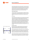
Both production loops feed into the now common distribution loop.
Depending on the flows from the production facility distribution pumps,
loads could be served by either plant.