


System Design Options
SYS-APM001-EN Chiller System Design and Control 31
1.90 power, respectively. The examples here use the more conservative 1.85
power:
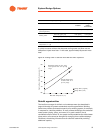
DP2/DP1 = (Flow2)/(Flow1)
1.85
Given different flow rates and entering water temperatures, a different
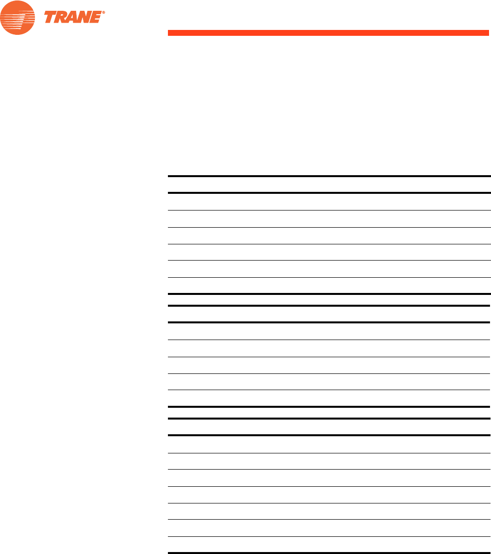
cooling tower can be selected for the low-flow condition (Table 6):
* Low-flow conditions represented in Table 5 through Table 8 are 1.5 gpm/ton [0.027 L/s/kW] chilled water
and 2.0 gpm/ton [ 0.036 L/s/kW] condenser water.
Table 5. Low-flow conditions for chilled-water pump
Base Case Low Flow*
Flow rate, gpm [L/s] 1,080 [68.1] 675 [42.6]
System pressure drop, ft water [kPa] 80.0 [239] 33.5 [100]
Evaporator-bundle pressure drop, ft water [kPa] 29.7 [88.8] 12.6 [37.7]
Pump power output, hp [kW] 39.9 [29.8] 10.5 [7.80]
Pump electrical power input, kW 32.0 8.4
Table 6. Low-flow conditions for cooling tower
Base Case Low Flow*
Flow rate, gpm [L/s] 1,350 [85.2] 900 [56.8]
Static head, ft water [kPa] 19.1 [57.1] 12.6 [37.7]
Tower fan power output, hp [kW] 30.0 [22.4] 20.0 [14.9]
Tower fan electrical power input, kW 24.1 16.0
Table 7. Low-flow conditions for condenser-water pump
Base Case Low Flow*
Flow rate, gpm [L/s] 1,350 [85.2] 900 [56.8]
System pressure drop, ft water [kPa] 30 [89.7] 14.2 [42.5]
Condenser-bundle pressure drop, ft water [kPa] 19.9 [59.5] 9.6 [28.7]
Tower static lift, ft water [kPa] 19.1 [57.1] 12.6 [37.7]
Pump power output, hp [kW] 31.4 [23.4] 11.0 [8.2]
Pump electrical input, kW 25.2 8.8