


System Configurations
SYS-APM001-EN Chiller System Design and Control 45
percent of the system load. At system loads greater than 50 percent, the
upstream chiller is preferentially loaded because it will attempt to produce
the design leaving chilled-water temperature. Any portion of the load that
remains is directed to the downstream chiller.
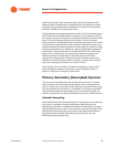
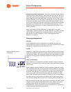
If chiller setpoints are staggered (upstream at 49°F [9.4°C] and downstream at
42°F [5.5°C]), the downstream chiller is loaded first. The upstream machine
then meets any portion of the system load that the downstream chiller cannot
meet. This control strategy offers several benefits. The first is that the
upstream chiller is always operating at an elevated temperature. This allows
it to operate at a higher efficiency. Also, placing an absorption chiller in the
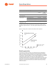
upstream position increases its capacity. As an example, an absorption chiller
that can produce 500 tons [1,760 kW] at a leaving chilled-water temperature
of 44°F [6.6°C] may produce 600 tons [2,110 kW] at 50°F [10°C]. Centrifugal,
helical-rotary, reciprocating, and scroll chillers experience capacity and
efficiency changes to a lesser degree. By judicious use of the series
configuration, these benefits can provide reduced installed cost and fuel
flexibility to the building owner. While not shown, a single manual bypass
with proper valving can provide for servicing of chillers.
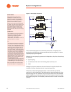
Equal loading of the two chillers may be accomplished by using a chiller
plant management system to dynamically reset the upstream chiller’s
setpoint in response to changes in system load.
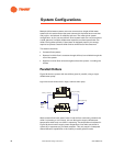
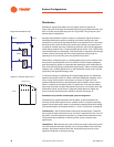
Primary–Secondary (Decoupled) Systems
The root cause of the difficulties with parallel chiller control in a constant
volume system is the fixed relationship between chiller- and system-flow
rates. If, instead, we can hydraulically decouple the production (chiller) piping
from the distribution (load) piping, it is possible to control them separately.
The fixed relationships are then broken apart. The production pumps are
typically constant volume, while the distribution pumps are variable volume.
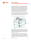
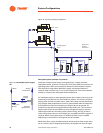
Hydraulic decoupling
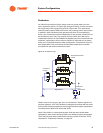
Figure 28 shows the basic decoupled system. This strategy is also referred to
as a primary–secondary pumping arrangement. Separate pumps are
dedicated to production and distribution. While the same water is pumped
twice (by different pumps), there is no duplication of pumping energy. This is
because the production pumps overcome only the chiller and production-
side pressure drop while the distribution pumps overcome only the
distribution system pressure drop.