


System Configurations
SYS-APM001-EN Chiller System Design and Control 51
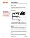
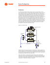
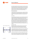
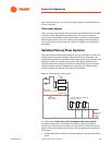
show a deficit and the pump will be cycled on again. The amount of surplus
flow necessary depends on the size of the chiller to be shut off. The surplus
flow must exceed a certain quantity before shutting off a chiller–pump pair. If
all chillers are equal in size, the surplus-flow signal can be a constant value.
Control of the number of chillers is accomplished by simply noting the
direction of flow in the bypass line. Thus, the system operates as a flow-
based demand system, not a temperature-based demand system.
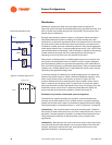
Flow-based control
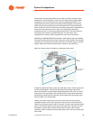
To properly operate a primary–secondary system, an indication of direction
of flow and the flow rate through the bypass line is necessary. This may be
done either directly or indirectly. When bypass flow is from supply to return,
it is called surplus. Bypass flow moving from return to supply is termed
deficit.
Flow-sensing
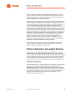
Direct flow-sensing in the bypass line can be accomplished in several ways. A
number of flow-metering technologies have been used successfully. These
include Pitot tube, venturi, orifice plate, differential pressure, turbine,
impeller, vortex, magnetic, and ultrasonic transit-time. The accuracy, ease of
installation, maintainability, and cost of meter technologies vary widely. To
give accurate results, a flow meter must be calibrated periodically, with some
flow meters requiring more-frequent calibration than others. When using
flow-sensing devices, it is important to understand the range of flows a
device can properly measure and its calibration requirements. The readings
will only be as good as the instrumentation. Also note that many flow-
measurement devices require several diameters of straight pipe for accurate
readings.
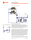
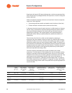
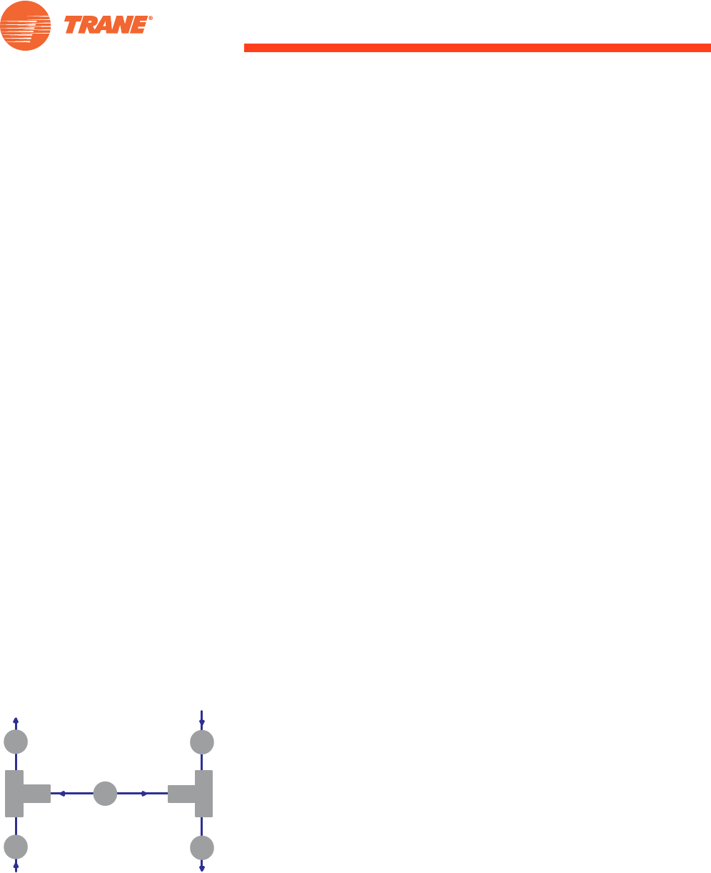
Temperature-sensing
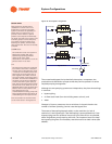
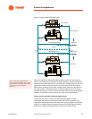
Mixed water streams at the outlets of the supply- and return-water tees
(Figure 35) can be used to indirectly determine the supply–demand
relationship. Standard temperature-mixing equations can be used to
determine the exact amount of surplus or deficit flow in the bypass line.
The five temperatures sensed—at points A, B, C, D, and E—are received by a
programmable controller. (Some control systems use only two sensors, at
points B and D, in conjunction with “pre-programmed” algebraic mixing
equations.) Processing software applies the classic mixing equations and
determines the resulting action to properly control the chilled-water system.
Note that sensor D needs to be very accurate, especially if there are many
chillers, since small temperature changes may warrant chiller sequencing.
Either temperature-sensing strategy has a cost and flexibility advantage if a
building or chiller-plant management system already exists or is planned.
D
C
A
D
BE
Figure 35. Temperature-sensing
(Required)
(Optional)
(Optional)
(Optional)
(Required)
Return Main
Supply Main