


System Configurations
SYS-APM001-EN Chiller System Design and Control 59
Small packaged chillers typically offer less design flexibility than larger
machines. It may not be possible to select a small packaged chiller with a
minimum flow rate of less than 60 percent of the design system flow… but
don’t let this deter you from designing a VPF plant that includes small
packaged chillers. Remember, pump power drops with the cube of the
reduction in flow, so even a modest 20 percent decrease in flow results in a
50 percent pump energy reduction. A 40 percent flow reduction yields an 80
percent pump energy reduction. The key to making variable flow with limited
flow turndown work properly is devising a plant layout and sequencing
strategy that accommodates the chiller’s minimum evaporator-flow limit.
Managing transient water flows
The second requirement of the selected chillers is proper control during
“transient flows.” This situation refers to the hydraulic effects caused by an
isolation valve when it opens (before the associated chiller starts) or closes
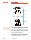
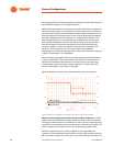
(after the chiller stops). To illustrate what happens, let’s look at an example.
Assume that the two-chiller VPF system in Figure 37 is designed for a 16°F
[8.9°C] T and that it delivers 40°F [4.4°C] chilled water. The temperature of
the return water remains relatively constant at 56°F [13.3°C], provided that
the coils and two-way valves function properly. Only Chiller 1 operates when
the cooling load is low; the isolation valve for Chiller 2 remains closed.
As the cooling load increases, the pump controller increases the rate of
chilled water flow through the system. Chiller 2 starts when Chiller 1 can no
longer produce 40°F [4.4°C] water. Opening the isolation valve for Chiller 2
almost instantly reduces the flow rate through Chiller 1 by half (Table 14),
which effectively doubles the T. Chiller 1’s controller will unload the machine
as quickly as possible, but in the interim, it will attempt to produce a 32°F T
[0°C] and cool the water to 24°F [-4.4°C]. If the chiller cannot unload quickly
enough, built-in fail-safes should stop and lock out the chiller before damage
occurs… but at the expense of satisfying the cooling load. The system can be
designed and operated to keep this scenario from occurring. This information
is provided in the following sections.
Select for the greatest tolerance to large changes in flow rate. The objective
is to simplify system control by minimizing the need for “supplemental”
demand limiting or valve control as chillers come online. Chillers that are
well-suited for variable primary flow can tolerate and respond to rapid flow-
Table 14. Flow-rate changes that result from isolation-valve operation
Number of operating chillers
12345
Flow-rate reduction when an isolation valve
opens*
50% 33% 25% 20% 17%
*Flow-rate reduction is expressed as a percentage of the actual chilled water flow rate
prior to transition:
% flow-rate reduction = 1–
number of chillers operating
number of chillers operating +1