


System Configurations
SYS-APM001-EN Chiller System Design and Control 55
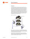
with a surplus that may, or may not, be large enough to indicate stopping a
chiller in that plant.
Other plant designs
There are many other ways to connect chillers to distributed loops and each
provides its own challenges and opportunities. The advent of variable-
primary-flow chilled-water systems offers some new opportunities as does
distributed pumping. In any case, getting system design advice specific to
your system early in the process can prevent or identify many operational
challenges.
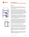
Variable-Primary-Flow Systems
Two main physical differences distinguish this type of system from the more
familiar primary–secondary design, which hydraulically “decouples” the
constant-flow production side of the chilled-water loop from the variable-flow
distribution side. The variable-primary-flow (VPF) design eliminates the
constant-flow chiller pumps and uses the variable-flow pumps to circulate
water throughout the entire chilled water loop (Figure 37). Both systems
include a bypass line, but the VPF bypass will be smaller.
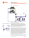
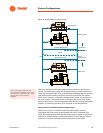
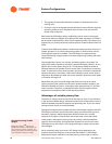
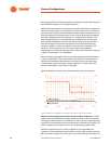
Figure 37. Variable-primary-flow system
In a VPF system, water flow varies throughout the entire system—
through the evaporator of each operating chiller as well as through the
cooling coils. Two-way control valves on coils, check (or isolation) valves on
chillers, and a bypass pipe with a control valve are required to implement a
VPF system.
• Variable-flow chiller pumps eliminate the need for a separate distribution
pump.
Typ
Chiller 1
Chiller 2
Isolation Valves
Flow Meter
(Alternative to Chiller P)
Modulating
Control Valve
Airside Coils with Two-Way
Control Valves
Bypass Line
Alternate
Location
Bypass Line