


58 Chiller System Design and Control SYS-APM001-EN
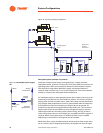
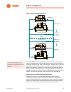
System Configurations
Experience with actual VPF plants indicates that a minimum evaporator-flow
limit of 60 percent for packaged chillers and 40 percent or less for configured
chillers work well.
Chiller manufacturers specify minimum and maximum limits for evaporator
water flow. Their objective?
• To promote good heat transfer and stable control (minimum flow limit)
• To deter vibration and tube erosion (maximum flow limit)
In the past, the typical range for water velocity in a chiller was 3 to 11 feet per
second. Today, manufacturer-conducted testing shows that specific chillers
may accommodate evaporator flow rates as low as 1.5 feet per second,
depending on tube type. This is good news for VPF systems because it
extends the chiller’s ability to operate effectively without the addition of
bypass flow.
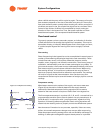
The minimum flow limit for a chiller can be lowered by selecting an
evaporator with more passes (a common option for machines with cooling
capacities of 150 tons or more). Granted, more passes may require a higher
evaporator pressure drop and more pumping power (Table 13). However, as
the system flow rate decreases, the evaporator pressure drop also decreases
by approximately the square of the flow rate reduction. Therefore, the pump
requires less extra power to work against the pressure drop as the system
flow rate drops below the design value.
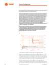
The other benefit of the added pass is better turndown with a wider
evaporator T, which starts at a lower design flow rate for the same cooling
capacity. In the case of the two-pass chiller, when using a 15° T, the chiller
invoked minimum flow prior to reaching the 50 percent system flow rate. This
could cause a more complicated transition from one to two chillers, as
discussed in the sections on “Managing transient water flows” on page 59
and “Chiller sequencing in VPF systems” on page 63. The other issue is that
more pumping energy will be used in the system that requires bypassed flow
more of the time.
Table 13. Effect of number of passes on minimum evaporator flow and pressure drop at reduced flow with packaged chillers
1
Design
flow rate
gpm [L/s]
Evap. pressure
drop at design
flow, ft.water
[kPa]
Evap. pressure
drop at 80%
flow rate,
ft.water [kPa]
Evaporator pressure
drop at 50% flow rate,
ft. water [kPa]
Minimum flow
rate, gpm [L/s]
Evaporator pressure
drop at minimum
flow rate, ft. water
[kPa]
2 pass 180 [11.4] 13.7 [40.9] 9.0 [26.9] 3.5 [10.5] 77 [4.9] 2.6 [7.8]
3 pass 180 [11.4] 42.6 [127.3] 28.7 [85.8] 11.9 [35.6] 52 [3.3] 4.0 [12.0]
2 pass
(15° T)
113 [7.4] 5.6 [16.7] 3.5 [10.5] flow too low, use min.
2.5 [7.5]
77 [4.9] 2.5 [7.5]
3 pass
(15° T)
116 [7.3] 19.6 [58.6] 12.8 [38.3] 5.0 [14.9] 52 [3.3] 4.0 [12.0]
1 Chillers may have slight differences in capacity, depending on which variable (flow, capacity, or T) is allowed to adjust.