


System Configurations
SYS-APM001-EN Chiller System Design and Control 65
Controlling transient flows is mandatory, regardless of plant size. The
number of chillers in the plant will not alter the degree of care needed to
properly manage transient flow-rate changes because the transition from one
operating chiller to two is inevitable in almost all plants.
Temporarily unload the operating chillers before starting the next one.
Reduce shock resulting from transient flows by unloading the operating
chillers before opening an isolation valve to bring another chiller online.
You can accomplish this by imposing a demand limit of 50 to 60 percent on
the operating chillers, or by raising the chilled water setpoint one to three
minutes before the isolation valve actuates. (See sidebar.)
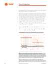
Open the chiller isolation valves slowly to encourage stable operation. How
slowly? That depends. If the chiller controller can only handle a flow-rate
change of 2 percent per minute, then the isolation valve must take 25 minutes
to open… far too long for most applications. Besides helping with chiller
stability, slow valve operation reduces the likelihood of valve-induced water
hammer in the piping system.
With sophisticated chiller controls, a 30-percent-per-minute change in the rate
of flow should work well in most applications. At this rate, the isolation valve
will transition from fully closed to fully open in about two minutes.
18
Like the bypass valve, be sure to select isolation valves that maintain a linear
relationship between valve position and flow rate.
The bottom line is that control of VPF systems must be considered during
system design.
Subtracting a chiller in a VPF system
Subtracting a chiller in a VPF system is not simple, either. It is important to
devise a “stop” strategy that protects the chillers from short-cycling.
Knowing when to stop a chiller (to provide sufficient downtime between
chiller starts) often is more challenging than knowing when to start it. The
most reliable way to do so—assuming that the VPF system is properly
installed, calibrated, and maintained—is to monitor the power draw of the
operating chillers.
(See sidebar.) Most unit controllers measure running load
amps (RLA) at regular intervals. The %RLA (actual RLA divided by design
RLA) provides a good indication of the present chiller load.
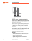
Base the “stop” strategy for a multi-chiller plant with equally sized machines
on the sum of the present %RLA for all chillers divided by the number of
operating chillers minus one. If the result is less than the desired capacity for
the operating chiller(s), then stop one of the machines.
For example, suppose that a plant consists of three equally sized chillers,
each of which is presently running at 60 percent of full-load capacity. If one
chiller is shut off, the two chillers still online would operate at approximately
90 percent of full-load capacity; (60% + 60% + 60%) / (3-1) = 90%. Having the
remaining two chillers operating almost fully loaded risks the need to restart
a chiller if the load increases.
In his article, “Primary-Only vs. Primary-
Secondary Variable Flow Systems,”
Steven T. Taylor, principal of Taylor
Engineering LLC, notes that unloading
the active chillers before starting
another produces warmer chilled water.
Although the temperature increase
seldom causes problems for comfort
cooling, it may be unacceptable in
industrial/process applications.
17
Sequencing based on load
Some plant operators prefer to sequence
chillers by comparing the actual system
load with the total plant capacity that
would result if a chiller is turned off.
However, this method can be less
reliable than one based on power draw
because flow- and temperature-sensing
devices require periodic recalibration to
correct for drift.