


60 Chiller System Design and Control SYS-APM001-EN
System Configurations
rate changes (Table 14). Selecting chillers with these characteristics improves
the likelihood of stable, uninterrupted operation.
Estimate the expected flow-rate changes and make sure that the chillers you
select can adapt to them. For example, one of the newest unit controllers on
the market can reliably maintain the desired chilled water temperature with a
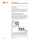
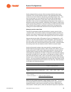
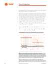
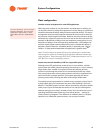
flow-rate reduction of 50 percent per minute. Figure 38 shows the response
of a chiller equipped with this controller in a more extreme situation. The
flow dropped 67 percent in 30 seconds, with limited effect on the leaving
chilled water temperature. Another, less robust chiller controller permits
flow-rate changes of less than 2 percent per minute and would need 25
minutes to adapt to a flow-rate reduction of 50 percent. Fluctuations of 2
percent or more are typical, even during normal system operation.
Attempting to limit flow-rate changes to this extent while starting or stopping
a chiller is impractical, if not impossible.
When comparing prospective chillers, consider the transient-flow tolerance
of the unit controllers. Then work closely with the chiller manufacturer to
devise a flow-transition sequence that accounts for the unique operating
characteristics of both the chiller and the application. Transient flow rate
control is discussed in more detail on page 65.
Figure 38. Example of chiller control responsiveness to flow-rate reduction*
*Data represents a Trane AdaptiView™ and CH530 chiller controller with flow compensation.
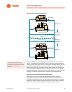
Select for nearly equal pressure drops across all chiller evaporators. A VPF
design loads and unloads the chiller(s) based primarily on the rate of water
flow through the evaporator. If a difference in size or type of evaporator gives
one chiller a lower pressure drop than the others in the plant, that chiller will
receive a higher rate of water flow and a correspondingly greater load.
Dissimilar pressure drops can make it difficult to provide stable plant
operation. Table 15 demonstrates this effect in a two-chiller system (similar to
the one shown in Figure 37). In this case, more water flows through Chiller 1’s