


64 Chiller System Design and Control SYS-APM001-EN
System Configurations
flow nears the maximum limit for the operating chiller(s), another machine
must be brought online. Similarly, as the system load and flow decrease,
chillers must be shut down to reduce the need for bypass water flow.
Adding a chiller in a VPF system
The simplest way to control a VPF system is to monitor the leaving-
evaporator water temperature and allow the operating chiller(s) to load
almost fully before bringing the next chiller online. As long as the system can
maintain the target temperature, there is no need to activate another chiller.
When the operating chiller(s) no longer provide enough cooling, the plant
controller should start the next chiller. For example, when the temperature
exceeds the design setpoint by a certain amount (for example, 1.5°F [0.8°C])
for a set time (for example, 15 minutes) an additional chiller starts.
One caveat: The next chiller should start before the chilled water flow reaches
the maximum limit of the operating chiller(s), even if the operating chillers
are not yet fully loaded. (This would rarely happen; most pipe velocity limits
are below that of the chillers.)
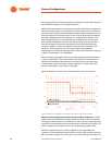
As chillers are brought online, flow rates may fluctuate substantially, and this
occurs quite often in a system with two chillers. All systems, with any
number of chillers, will find the most difficult transition when adding or
subtracting the second chiller. An example will help explain the challenges.
.
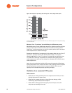
At a point in time, Chiller 1 is active and has 1,100 gpm [69.4 L/s] flowing
through its evaporator. It can no longer satisfy the required system supply
temperature. What happens if Chiller 2’s valve is opened with no other action
taken? If we assume that pressure drops are equal, 550 gpm [34.7 L/s] will
flow through each chiller. This means Chiller 1’s flow rate drops by 50 percent
as fast as Chiller 2’s isolation valve opens (probably beyond what its controls
can respond to) and we are below each chiller’s minimum flow rate. Be aware
that this could become an issue since chiller controls may protect the chiller
by shutting it off. The result is that some combination of pump speed, bypass
valve control, and slow-acting valves at the chillers must do two things:
• Keep change in flow rate within the equipment limitations
• Keep each chiller’s flow rate above its minimum
Table 16. Flow-rate-fluctuation examples
Design
flow rate
gpm [L/s]
Minimum
flow rate
gpm [L/s]
Maximum
flow rate
gpm [L/s]
Chiller 1 960 [60.6] 576 [36.3] 2,110 [133.1]
Chiller 2 1,440 [90.8] 675 [42.6] 2,474 [156.1]