


48 Chiller System Design and Control SYS-APM001-EN
System Configurations
Distribution
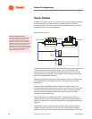
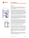
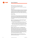
Distribution pumps take water from the supply water tee (point B in
Figure 29), push it through all the distribution piping and load terminals, and
then on to the return water tee (point A in Figure 29). This pump can (and
should) allow variable flow.
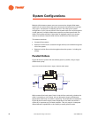
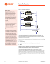
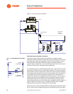
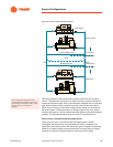
By itself, the distribution system is easy to understand. Figure 30 shows a
simplified distribution system consisting of multiple cooling coils, each
controlled by a valve that regulates the flow in its respective coil. In this case,
the flow control valves should not be three-way because a constant flow is
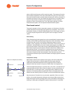
not desired. Instead, two-way modulating valves are used. As the aggregate
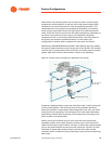
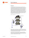
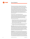
loads change system flow, a constant speed pump would “ride” its flow-rate
versus head-pressure relationship. This means that in response to the change
of flow required, the pump will find a new equilibrium point along its
operating curve (move from point A to point B in Figure 31).
Alternatively, multiple pumps or variable-speed pumps can be used to limit
the dynamic pumping head, similar to VAV fan control. Properly designed,
part-load pumping power can approach the theoretical cubic relationship to
flow, thus reducing energy consumption significantly. Today, most decoupled
systems use a variable-speed drive on the distribution pump, and it may be
required by the applicable energy code.
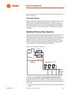
A common strategy for operating the variable speed pump is to adjust the
speed of the pump’s motor to create a sufficient differential pressure, P, a t
one or more critical points in the system, as shown in Figure 33. This
pressure difference tends to decrease when the air-handler control valves
open in response to increasing loads. To restore the P across the system,
the pump controller increases the speed of the pump. Conversely, when the
air-handler control valves close in response to decreased coil loads, the
pump controller slows the pump speed to maintain the target P.
Distribution-loop benefits of decoupled system arrangement
The distribution system benefits from the ability to accommodate load
diversity, the fact that system flow is variable, and (in a properly operating
system) the fact that return water is maintained at temperatures near design.
The last assumption is discussed further in “Low T syndrome” on page 79.
Load diversity. Not all chilled-water loads peak simultaneously. Therefore,
the quantity of water that flows at any one time is reduced from the “sum of
the peaks” load that would be required in a constant-flow distribution loop.
This presents the possibility of reducing chiller, pump, and pipe sizes
significantly.
Variable flow. Because two-way control valves are used on the cooling coils,
only the water that the loads actually use is pumped. Most of the time, this
means a significantly reduced flow rate, accompanied by an even more
significant reduction in pumping energy.
SupplyReturn
Bypass Line
Loads
Distribution
Figure 30. Distribution loop
Pump Curve
Head
Flow
Figure 31. Example pump curve
B
A