


62 Chiller System Design and Control SYS-APM001-EN
System Configurations
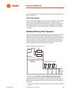
Accurate flow measurement
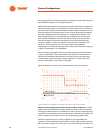
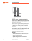
The success of a variable-primary-flow installation depends on the quality of
the flow-measuring device that controls the system bypass valve (and
perhaps also indicates the plant load). Some practitioners use a flow meter
16
to directly detect the flow rate (C in Figure 37); others use a differential
pressure sensor (D) that monitors the change in water pressure across the
chiller evaporator and then correlates the pressure differential to a water flow
rate.
Select a flow measurement device with accurate and repeatable
measurements. Regardless of which type of device you use, the flow meter
or differential pressure sensor must be of high quality; that is, the device
must provide accurate and repeatable measurements. For the plant to
operate well, the device also must remain calibrated and perform reliably
over time. Purchase prices vary widely, but the adage “you get what you pay
for” typically holds true. In our experience, the cost of a suitable flow-
measuring device is closer to $1,000 USD than to $100 USD. Put simply, don’t
compromise on accurate sensing devices when negotiating potential cost
reductions during the “value engineering” phase of a project.
One further caveat about measurement accuracy: Proper installation is
critical to ensure accurate readings. If the manufacturer states that at least 10
pipe diameters of uninterrupted flow are required both upstream and
downstream of the sensing device, then make sure that the piping layout
complies.
Select an accurate proof-of-flow device for each chiller. Flow reductions
through chillers in VPF systems often cause paddle-type flow switches to
flutter or open altogether, which shuts down the chiller. To provide accurate,
reliable confirmation of flow, select a sensitive pressure-differential switch
(or other high-quality device) and install it properly, piping it across the
evaporator.
Bypass locations
A bypass is required whether the primary flow is constant or variable. In a
primary–secondary system, the decoupler allows excess primary water to be
bypassed. In the VPF system, the bypass allows excess flow only when
needed to maintain the chillers' minimum flow requirements.
There are three common locations for the VPF bypass line:
• Place the smaller bypass required for a VPF system in the same position
as the bypass in a “decoupled” system. A variable-speed drive on the
pump located near the chillers reduces flow and allows substantial
energy and operating cost savings. One drawback is that the valve must
work against higher pressures—possibly causing wear and lack of
controllability.
• Use three-way valves at some of the system coils. While this approach
ensures minimum chiller flow, it reduces the pump operating cost-
savings, due to the increased system flow and decreased return-water
temperature.