


System Configurations
SYS-APM001-EN Chiller System Design and Control 47
Production
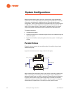
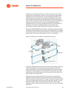
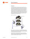
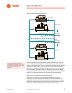
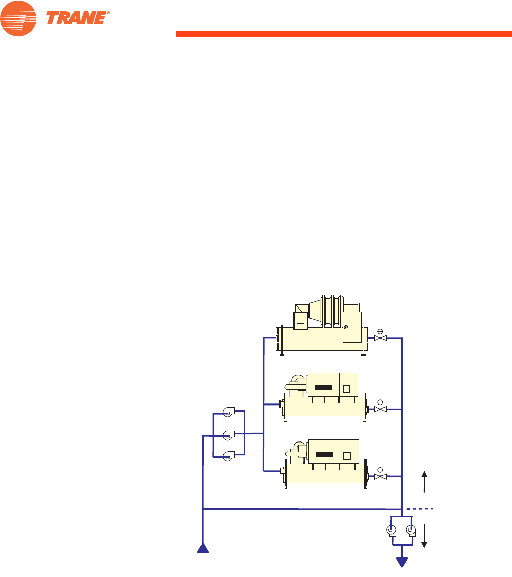
An individual production (chiller) pump need only pump water from the
return bypass tee (point A in Figure 29), through its chiller, and into the tee at
the supply-end of the bypass line (point B in Figure 29). This represents a
relatively small pressure differential and a low pumping-power requirement.
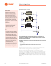
In addition, each individual pump operates only when its corresponding
chiller runs. Production loops are independent of one another, as well as from
the distribution loop. They may consist of pump–chiller pairs that act as
independent chillers. Or, manifolded and stepped pumps can be teamed with
automatic, two-position chiller valves to operate in the same way as pump–
chiller pairs. Figure 29 shows the latter arrangement. Temperature control is
also independent. The conventional chilled-water temperature controller
furnished with the chiller serves this function.
Figure 29. Production loop
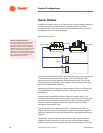
Chillers may be of any type, age, size, or manufacturer. System operation is
simplest, however, if all of the chillers are designed to operate with the same
leaving chilled-water temperature and through the same system temperature
rise (temperature difference) across the chiller.
Note: If the chillers in a decoupled system make the same chilled-water
temperature, then all the operating chillers are loaded to equal percentages.
There may be times when preferentially loading a chiller is desired. This is
discussed in “Preferential Loading” on page 73.
Production
Pumps
Chiller 3
Chiller 2
Chiller 1
Bypass Line
Return
Production
Distribution
Supply
A
B
Automated Isolation
Valves