


System Configurations
SYS-APM001-EN Chiller System Design and Control 61
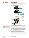
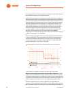
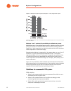
evaporator because its selection pressure drop is lower than that of Chiller 2.
Load is proportional to flow rate and temperature difference, tons = (gpm ×
T) / 24. Because Chiller 1 is asked to satisfy a load that exceeds its capacity,
it cannot satisfy the chilled water setpoint when the return water temperature
equals the design condition. Meanwhile, Chiller 2 is less than fully loaded.
Balancing the system at the design condition, for example, by installing a
balancing valve in series with Chiller 1, reduces this problem and works well
at design and part load conditions. Alternatively, you could increase the load
on Chiller 2 by lowering its chilled water setpoint; however, this complicates
system control. The simplest solution is to select chillers that have (nearly)
equal pressure drops at their design flow rates, whether the capacities are
the same or not.
System design and control requirements
If experience has taught us anything about implementing variable primary
flow, it’s this: The single, most important contribution of the engineer is to
provide written, detailed descriptions of the plant’s sequence of
operation.
These descriptions should include control sequences for:
• Full- and part-load operation
• Minimum and maximum flow-rate management
• Transient flow-rate changes
• Starting and stopping chillers
Furthermore, this information must be shared early in the design process.
Without specific, documented sequences of operation, it is unlikely that the
controls provider will devise programs that operate the plant as intended.
Bottom line: VPF plants that work result from close, early-on collaboration
between the engineer, the chiller manufacturer, and the controls provider.
Variable primary flow is a value-added option that can help your clients curb
operating costs at a lower initial cost than traditional primary–secondary
designs … but only if you select the right components, install them properly,
and operate them in accordance with a well-thought-out control scheme.
Table 15. Effect of dissimilar evaporator pressure drops
Capacity,
tons
Flow rate, gal/min Pressure drop, ft H
2
0*
Selection Actual Selection Actual Change, %
Chiller 1 500 750 819 12 14.3 +9.2
Chiller 2 300 450 381 20 14.3 -15.3
*Values shown here are based on the assumption that pressure drop changes with the square of the flow
rate.